Ques 21. The phase difference between voltage and current wave through a circuit element is Given as 30°. The essential condition is that
Both waves must have same frequency
Both waves must have identical peak values
Both waves must have zero value at the same time
None of the above
Answer.1. Both waves must have same frequency
Explanation:
The current and voltage must have same frequency for any real power to be dissipated.
Ques 22. The r.m.s. value of a sinusoidal A.C. current is equal to R.M.S value at an angle of______degrees.
90°
60°
45°
30°
Answer.3 45°
Explanation:
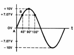
Three values are used to describe alternating current; peak, average, and root-mean-square (rms). The maximum point on a sine wave is the peak value. A peak value of 100 V means that the peak-to-peak value is 200 V.
The average of all instantaneous values of a generator is measured at regular intervals. The values are taken at selected points in the generating process. The average of these is the average value of AC current. The average value is 0.637 times the peak.This means that a peak of 100 V is equal to 63.7 V average.
We could get the R.M.S value or 0.707 by taking the sine of 45°.
Ques 23. Capacitive reactance is more when
Capacitance is less and frequency of supply is less
Capacitance is less and frequency of supply is more
Capacitance is more and frequency of supply is less
Capacitance is more and frequency of supply is more
Answer.1. Capacitance is less and frequency of supply is less
Explanation:
Capacitive reactance is given as:
Xc = 1/2πfC
Where Xc = reactance in ohms
F = frequency in hertz
C = capacitance in farads.
Therefore capacitive reactance is inversely proportional to both frequency and capacitance.
Capacitive reactance increase with decreasing frequency because the longer cycle period means more current will flow resulting in more energy change during each cycle.
Ques 24. In a series resonant circuit, the impedance of the circuit is
Minimum
Maximum
Zero
None of the above
Answer.1. Minimum
Explanation:
At resonance, the inductive reactance is equal to capacitive reactance and hence the voltage across inductor and capacitor cancel each other. Hence the total impedance o the circuit is resistance only. So, the circuit behaves like a purely resistive circuit.
Therefore at resonance current, I = V / R, therefore the current at the resonant frequency is maximum as a resonance in impedance of the circuit is resistance only, therefore, it is minimum.
Ques 25. Which of the following circuit component opposes the change in the circuit voltage?
Inductance
Capacitance
Conductance
Resistance
Answer.2. Capacitance
Explanation:
Capacitors are said to “oppose voltage change.” because it takes time for charges to build upon the capacitor plates when a voltage is applied, and it takes time for the charge to leave the plates once the voltage is removed,
This just means that if you suddenly change the voltage applied to a capacitor, it can’t react right away; the voltage across the capacitor changes more slowly than the voltage you applied.
Ques 26. The best place to install a capacitor is
Very near to inductive load
Across the terminals of the inductive load
Far away from the inductive load
Any where
Answer.2. Across the terminal of the inductive load
Explanation:
By connecting several capacitors in parallel, the resulting circuit is able to store more energy since the equivalent capacitance is the sum of the individual capacitance of all capacitors involved. C=C1+C2+C3+……+Cn.( because Q=CV).
The voltage applied to parallel connection is the minimum voltage rating of one of the capacitors.
Capacitors hate voltage fluctuations which are prevalent in series circuit as opposed to the parallel circuit
Also, capacitors try to reach a common potential when connected in series.
Ques 27. Poor power factor
Reduces load handling capability of electrical system
Overloads alternators, transformers and distribution lines
Results in more voltage drop in the line
Results in all above
Answer.5. All of the above
Explanation:
Effect of Poor Power Factor
Large Line Losses (Copper Losses)
For a given cross-sectional area of the line conductors, line losses are proportional to 1/cos2Φ.Poor power factor means more line losses and low transmission efficiency.
2. Large kVA rating and Size of Electrical Equipments
Electrical Machinery (Transformer, Alternator, Switchgears etc) rated in kVA. Power factor is inversely proportional to the kVA i.e. CosФ = kW / kVA. So at low power factor, the KVA rating of the equipment increases, making the equipment larger and expensive.
3.) Greater Conductor Size and Cost
In case of low power factor to transmit high current, higher conductor size transmission lines are needed.
4. Poor Voltage Regulation and High Voltage Drop
We know that Voltage Drop = V = IZ.
The large current at low lagging power factor causes greater voltage drops in alternators, transformers, and transmission lines.
5. Low Efficiency
At low power factor, the large current makes more I2R losses in all the elements of the supply system. Hence It leads to poor efficiency.
Ques 28. Capacitors for power factor correction are rated in
In all the three applications capacitor provides Reactive power(whichdeals with voltage) to the system.Since reactive power unit is KVAR(Kilo Volt Ampere Reactive) capacitor rating also measured in KVAR
Rating of Induction motor is in KW(its losses depends on current)
Rating of transformer is in KVA( its losses depends on voltage and current)
So,
Rating of capacitor bank is in KVAR (it deals with voltages)
Ques 29. In series resonant circuit, increasing inductance to its twice value and reducing capacitance to its half value
Will change the maximum value of current at resonance
Will change the resonance frequency
Will change the impedance at resonance frequency
Will increase the selectivity of the circuit
Answer.4. Will increase the selectivity of the circuit
Explanation:
Selectivity s the ability of a particular circuit to respond to a particular frequency by simply neglecting all other frequencies. Selectivity is measured by Q factor and for the series tuned circuit, it is the ratio of the inductive or capacitive reactance to the total resistance to the circuit. A high-Quality factor means high selectivity.
The resonant selectivity is determined as
So if the inductance is increased twice and capacitance is reduced to half the selectivity will increase 4 times.
Ques 30. Pure inductive circuit
Consumes some power on average
Does not take power at all from a line
Takes power from the line during some part of the cycle and then returns back to it during another part of the cycle
None of the above
Answer.3. Takes power from the line during some part of the cycle and then returns back to it during another part of the cycle
Explanation:
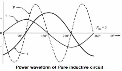
From the above waveform, we find that the power varies sinusoidally whose average value over a complete cycle is zero. Hence the power consumed by the purely inductive circuit is zero. This can be proved mathematically
We know that in Pure inductive circuit Voltage is leading 90 Degree from current i.e the phase difference between current and voltage is 90°