Ques 31. Inductance effects the direct current flow
Only at the time of turning off
Only at the time of turning on
At the time of turning on and off
At all the time of operation
Answer.3. At the time of turning on and off
Explanation:
Inductance is the property of generating an E.M.F of self-induction which opposes the change in the current. This opposing E.M.F of self-induction is also called as the counter E.M.F or back E.M.F.
When the circuit current reaches its maximum value, determined by the circuit voltage and resistance, it no longer changes in value and the field no longer expands, so that no emf of self-induction is generated. The field remains stationary, but, when the current attempt to rise or fall, the field will either expand or contract and generate a counter emf opposing the change in current flow.
For direct current, inductance affects the current flow only when the circuit is turned on and off or when some circuit condiflon is changed since only at those times does the current change in its value.
Ques 32. Inductance of a coil Varies
Directly as the cross-sectional area of magnetic core
Directly as square of number of turns
Directly as the permeability of the core
Inversely as the length of the iron path
Both 1 and 4
Answer.4. Both 1 and 4
Explanation:
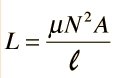
The inductance of a coil of wire is given by
Where N = Number of turns in the coil
μ = permeability of the core material
A = Area of the coil
l = length of the coil
COIL AREA: Greater coil area (cross-section of the core) results in greater inductance
COIL LENGTH: The longer the coil’s length, the less inductance the shorter the coil’s length, the greater the inductance.
Ques 33. All the rules and laws of D.C. circuit also apply to A.C. circuit containing
Capacitance only
Inductance only
Resistance only
All above
Answer.3. Resistance only
Explanation:
Many ac circuits contain resistance only. The rules for these circuits are the same rules that apply to dc circuits. Resistors lamps and heating elements are examples of resistive elements. When an ac circuit contains only resistance, Ohm’s Law, Kirchhoff’s Law, and the various rules that apply to voltage, current, and power in a dc circuit also apply to the ac circuit.
Ques 34. Time constant of an inductive circuit
Increases with increase of inductance and decrease of resistance
Increases with the increase of inductance and the increase of resistance
Increases with decrease of inductance and decrease of resistance
Increases with decrease of inductance and increase of resistance
Answer.1. Increase with increase of inductance and decrease of resistance
Explanation:
The ratio L/R is called as the time constant of the inductive circuit and gives the time in the seconds required for the circuit to rise to 63.2% of its maximum value.
Hence the time constant of the inductive circuit is directly proportional to the inductance and inversely proportional to the resistance.
Ques 35. Power factor of an inductive circuit is usually improved by connecting capacitor to it in
Parallel
Series
Either 1 or 2
None of the above
Answer.1. Parallel
Explanation:
In the industry, inductive loads draw a lagging current which in turn increases the amount of reactive power. ln this case, the KVA rating of the transformer and the size of the conductor should be increased to carry out the additional reactive power. Generally. Capacitors are connected in parallel with the load to improve the low power factor by increasing the power factor value. Capacitor draws leading current and partially or completely neutralizes the lagging reactive power of the load.
For further detail check the explanation of question number 26.
Ques 36. The mutual inductance between two unity coupled coil of 9H and 4H is
50 H
13 H
2.2 H
6 H
Answer.4. 6 H
Explanation:
Mutual inductance between two coils is
M = √L1L2
M = √ 9 x 4
M = 6
Ques 37. Power factor of the following circuit will be zero
Resistance
Inductance
Capacitance
Both 2 and 3
Answer.4. Both 2 and 3
Explanation:
If Current and Voltage are 90 Degree Out of Phase, Then The Power (P) will be zero. We know that Power in AC Circuit
P= V I Cos φ
In inductive circuit voltage leads the current by 90 degrees and in capacitive circuit, the current leads the voltage by 90 degrees
if the angle between current and Voltage are 90 ( φ = 90) Degree.
Power P = V I Cos ( 90) = 0
[ Note that Cos (90) = 0]
Ques 38. Power factor of the following circuit will be unity
Inductance
Capacitance
Resistance
Both 1 and 2
Answer.3. Resistance
Explanation:
As Explain in the above question
P= V I Cos φ
In pure resistive circuit, the voltage and the current are in the same phase, therefore, the angle between voltage and current is 0
hence
P = VI cos0
P = VI
Ques 39. Power factor of the system is kept high
To reduce line losses
To maximise the utilization of the capacities of generators, lines, and transformers
To reduce voltage regulation of the line
Due to all above reasons
Answer.4. Due to all of the above reason
Explanation:
Advantages of high power factor:
Increase in efficiency of system and devices
Low Voltage Drop
Reduction in size of a conductor and cable which reduces cost of the Cooper
An Increase in available power
Line Losses (Copper Losses) I2R is reduced
Appropriate Size of Electrical Machines (Transformer, Generators etc)
Eliminate the penalty of low power factor from the Electric Supply Company
Low kWh (Kilo Watt per hour)
Saving on the power bill
Better usage of power system, lines and generators etc
Saving in energy as well as rating and the cost of the electrical devices and equipment is reduced.
For more information check Question number 27.
Ques 40. The time constant of the capacitance circuit is defined as the time during which voltage
Falls to 36.8% of its final steady value
Rises to 38.6% of its final steady value
Rises to 63.2% of its final steady value
None of the above
Answer.3. Rises to 63.2% of its final steady value
Explanation:
An RC time constant tells us about the relation between time, resistance, and capacitance. The time taken by the capacitor is directly proportional to the amount of resistance and capacitance in the circuit.
The time constant reflects the time required for the capacitor to charged up to 63.2% of the applied voltage or to discharged down 36.8%