1. Which circuit can be used as a full-wave rectifier?
A. Absolute vale output circuit
B. Positive clipper with two diodes
C. Negative clipper with two diodes
D. Peak clampers
Answer: A
An absolute value output circuit produces an output signal that swings positively only, regardless of the polarity of the input signal; because of the nature of its output waveform, the circuit is used as a full-wave rectifier.
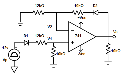
2. For the circuit shown below find the output voltage
A. Vo (+) = +10 v
B. Vo (+) = +12v
C. Vo (+) = +7v
D. None of the mentioned
Answer: B
The voltage at the terminal
V1 = (Vp -Vd1) /2
V1 = (12-0.7) /2 = 5.65 v (Vd1= voltage drop across diode=0.7)
Similarly, the voltage at the negative terminal
V2 = (Vo -Vd3 ) /2 = (Vo – 0.7) /2
Since Vid ≅ 0v , ∴ V1 = V2
Vo = (5.65 *2 ) + 0.7 = 12v.
4. What is the alternate method to measure the values of non-sinusoidal waveform other than ac voltmeter?
A. Clipper
B. Clamper
C. Peak detector
D. Comparator
Answer: C
A conventional ac voltmeter is designed to measure the RMS value of the pure sine wave whereas, the peak value of the non-sinusoidal waveforms can be a peak detector.
5. State the condition needed to be satisfied by the peak detector for proper operation of the circuit.
A. CRd ≤ T/10 and CRL ≥ 10T
B. CRd ≤ 10T and CRL ≥ T/10
C. CRd ≥ T/10 and CRL ≤ 10T
D. CRd ≥ 10T and CRL ≤ T/10
Answer: A
For proper operation of the circuit, the charging and discharging time constant must satisfy the following: CRd ≤ T/10 and CRL ≥ to 10T.
6. The resistor in the peak detector is used to
A. To maintain proper operation
B. Protect op-amp from damage
C. To get shaped non-sinusoidal waveform
D. None of the mentioned
Answer: B
The resistor is used to protect the op-amp against the excessive discharge current, especially when the power supply is switched off.
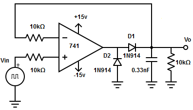
7. How the recovery time of the op-amp is reduced?
A. Diode is connected at the output of the amplifier
B. Load resistor
C. Forward biased diode resistor
D. Discharge capacitor
Answer: A
The diode-connected at the output of op-amp conducts during the negative half cycle of input voltage. Hence, prevent the op-amp from going into negative saturation. This in turn helps to reduce the recovery time of the op-amp.
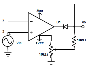
8. How to detect the negative peaks of input signals in the peak detector given below?
A. Reversing D1 diode
B. Reversing D1 and D2 diodes
C. Reversing D2 diode
D. Charging the positions of D1 and D2
Answer: B
The negative peaks of the input signal Vin can be detected by reversing diodes D1 and D2.
9. In the sample and hold circuit, the period during which the voltage across the capacitor is equal to the input voltage
A. Sample period
B. Hold period
C. Delay period
D. Charging period
Answer: A
The time periods of the sample and hold control voltage during which the voltage across the capacitor is equal to the input voltage are called the sample period.
10. During which period the op-amp’s output of sample and hold circuits is processed?
A. Delay period
B. Sample and hold period
C. Sample period
D. Hold period
Answer: D
The hold period is the period during which the voltage across the capacitor is constant and the output of the op-amp is processed or observed during hold periods.
11. Which IC is mostly preferred for a sample and hold circuits?
A. µ771
B. IC741
C. LF398
D. µ351
Answer: C
LF398 has a significant reduction in size and improved performance and requires only an external storage capacitor.
12. Sample and hold circuits are used in
A. Analog to Digital modulation
B. Digital to analog modulation
C. Pulse position modulation
D. All of the mentioned
Answer: D
All types of modulation involve taking samples of an input signal and hold on to its last sampled value until the input is sampled.
1. Which circuit is used for obtaining desired output waveform in the operational amplifier?
A. Clipper
B. Clamper
C. Peak amplifier
D. Sample and hold
Answer: A
In an op-amp clipper circuit, a rectifier diode is used to clip off certain portions of the input signal to obtain a designed output waveform.
2. The clipping level in op-amp is determined by
A. AC supply voltage
B. Control voltage
C. Reference voltage
D. Input voltage
Answer: C
The clipping level is determined by the reference voltage which should be less than the input voltage range of an op-amp.
3. In a positive clipper, the diode conducts when
A. Vinref
B. Vin = Vref
C. Vin > Vref
D. None of the mentioned
Answer: B
In a positive clipper, the diode conducts until Vin = Vref (during the positive half cycle of the input), because when Vinref, the voltage (Vref) at the negative input is higher than that at the positive input.
4. What happens if the potentiometer Rp is connected to a negative supply?
A. Output waveform below -Vref will be clipped off
B. Output waveform above +Vref will be clipped off
C. Output waveform above -Vref will be clipped off
D. Output waveform below +Vref will be clipped off
Answer: C
If the potentiometer Rp is connected to negative supply -VEE instead of +VCC, the reference voltage Vref will be negative. As a result, the entire output waveform above -Vref is to be clipped off.
6. What happens if the input voltage is higher than the reference voltage in a positive clipper?
A. Output voltage = Reference voltage
B. Output voltage = DC Positive voltage
C. Output voltage = Input voltage
D. All of the mentioned
Answer: A
When the input voltage is higher than the reference voltage, the op-amp operates in an open loop, and the diode becomes reverse biased. Thus, the output voltage will be equal to a reference voltage.
7. A positive small-signal halfwave rectifier can
A. Rectify signals with peak value only
B. Rectify signals with the value of few millivolts only
C. Rectify signals with both peak value and down to a few millivolts
D. None of the mentioned
Answer: C
A positive small-signal halfwave rectifier can rectify signals with peak values down to a few millivolts because the high open-loop gain of the op-amp automatically adjusts the voltage drive to the diode so that the rectified output peak is the same as the input.
9. Diode in small-signal positive halfwave rectifier circuit acts as
A. Ideal diode
B. Clipper diode
C. Clamper diode
D. Rectifier diode
Answer: A
The diode acts as an ideal diode since the voltage across the ON diode is divided by the open-loop gain of the op-amp. As the input voltage starts increasing in the positive direction, the output of the op-amp also increases positively till the diode become forward biased.