1. How an AC amplifier can be powered by a single supply voltage and produces voltage swing?
A. By inserting a voltage divider at the inverting input
B. By inserting a voltage divider at the non-inverting input
C. By inserting a voltage divider at the output
D. By inserting a voltage divider at the feedback circuit
Answer: B
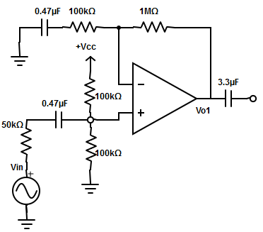
A positive dc level is intentionally inserted using a voltage-divider network at the non-inverting input terminal so that output can swing both positively as well as negatively.
2. Find the maximum output voltage swing of an AC inverting amplifier using op-amp 741C?
A. +15Vpp
B. ±15Vpp
C. ±13Vpp
D. +13Vpp
Answer: A
The value of power supply for 741 op-amp=±15v. Therefore, the ideal maximum output voltage swing for an AC amplifier with a single power supply = +Vcc = +15v.
3. Determine the lower cut-off frequency of the circuit.
A. 21.3Hz
B. 12.15Hz
C. 1.35Hz
D. None of the mentioned
Answer: D
The input resistance of the amplifier is RIF =(R2 ||R3) || [ri×(1+AB.] –> equ 1
As [ri×(1+AB.] >> R2
=> Therefore, equ 1 becomes
RIF ≅ R2 || R3 = 100kΩ || 100kΩ
= (100×100)/(100+100) = 50kΩ.
=> Rin = Ro = 150Ω.
∴ Lower cut off frequency
fL= 1/[2πCi×(RIF+Ro)]
= 1/[2π×0.47µF×(50kΩ+150Ω)] = 6.75Hz.
4. In differential op-amp configuration a subtractor is called as
A. Summing amplifier
B. Difference amplifier
C. Scaling amplifier
D. All of the mentioned
Answer: C
In a subtractor, input signals can be scaled to the desired values by selecting appropriate values for the external resistors. Therefore, this circuit is referred to as a scaling amplifier
5. How the peaking response is obtained?
A. Using a series LC network with op-amp
B. Using a series RC network with op-amp
C. Using a parallel LC network with op-amp
D. Using a parallel RC network with op-amp
Answer: C
The peaking response is the frequency response that peaks at a certain frequency. This can be obtained by using a parallel LC network with the op-amp.
6. The expression for the resonant frequency of the op-amp
A. fp = 1/[2π×√(LC.].
B. fp = (2π×√L)/C
C. fp = 2π×√(LC.
D. fp = 2π/√(LC.
Answer: A
The resonant frequency is also called peak frequency, which is determined by the combination of L and C.
fp = 1/(2π√LC).
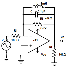
7. From the circuit given below find the gain of the amplifier
A. 1.432
B. 9.342
C. 5.768
D. 7.407
Answer: D
Frequency,
fp= 1/[2π×√(LC.]
=1/[2π√(0.1µF×8mH)]
=1/1.776×10-4= 5.63kHz.
=> XL = 2πfpL
= 2π×5.63kHz×8mH = 282.85.
The figure of merit of coil
Qcoil= XL/R1= 282.85/100Ω = 2.8285.
∴ Rp = (Qcoil)2 ×R1
= (2.82852)×100Ω= 800Ω.
The gain of the amplifier at resonance is maximum and given by
AF =-(RF||Rp)/R1
= -(10kΩ||800)/100Ω
=-740.740/100 = -7.407.
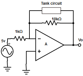
8. The parallel resistance of the tank circuit and for the circuit is given below. Find the gain of the amplifier?
A. -778
B. -7.78
C. -72.8
D. None of the mentioned
Answer: B
The gain of the amplifier at resonance is the maximum and given by,
AF =-(RF||Rp)/ R1
=-[(Rp×RF)/ (RF+Rp)] /R1
= -[ (10kΩ × 35kΩ)/ (10kΩ+35kΩ)] /1kΩ
=> AF =- 7.78kΩ/1kΩ= -7.78.
9. The band width of the peaking amplifier is expressed as
A. BW = (fp× XL)/ (RF+Rp)
B. BW =[ fp×(RF+Rp)× XL ] / (RF×Rp)
C. BW =[ fp×(RF+Rp)] / (RF×Rp)
D. BW = [fp×(RF+Rp) ]/ XL
Answer: B
The bandwidth of the peaking amplifier,
BW = fp/Qp,
where Qp – figure of merit of the parallel resonant circuit
= (Rf||Rp)/Xl = (Rf×Rp)/[(Rf+Rp)× Xl]
=> BW = [fp×(Rf+Rp)× Xl] / (Rf×Rp).
10. Design a peaking amplifier circuit to provide a gain of 10 at a peak frequency of 32khz given L=10mH having 30Ω resistance.
Answer: B
Given L=10mH and the internal resistance of the inductor R=30Ω. Assume R1=100Ω. The gain times peak frequency=