The mentioned answer can be obtained if the value of frequencies is substituted in the gain magnitude equation
Frequency
Gain of the filter
1. f H
i. VO/Vin ≅ AF
2. f=fH
ii. VO/Vin ≅ AF/√2
3. f>fH
iii. VO/Vin ≤ AF
|(Vo/Vin)|=AF/√(1+(f/fH)2).
23. Determine the gain of the first order low pass filter if the phase angle is 59.77o and the passband gain is 7.
A. 3.5
B. 7
C. 12
D. 1.71
Answer: A
Given the phase angle
φ =-tan-1(f/fH)
=> f/fH=- φtan(φ)
= -tan(59.77o)
=> f/fH= -1.716.
Substituting the above value in gain of the filter
|(VO/Vin)|
= AF/√ (1+(f/fH)2)
=7/√[1+(-1.716)2)] =7/1.986
=>|(VO/Vin)|=3.5.
24. In a low pass Butterworth filter, the condition at which f=fH is called
A. Cut-off frequency
B. Break frequency
C. Corner frequency
D. All of the mentioned
Answer: D
The frequency, f=fH is called cut-off frequency, because the gain of the filter at this frequency is down by 3dB from 0Hz. The cut-off frequency is also called break frequency, corner frequency, or 3dB frequency.
25. Find the High cut-off frequency if the passband gain of a filter is 10.
A. 70.7Hz
B. 7.07kHz
C. 7.07Hz
D. 707Hz
Answer: C
High cut-off frequency of a filter
fH = 0.707 × AF
= 0.707 × 10
=>fH=7.07Hz.
26. To change the high cutoff frequency of a filter. It is multiplied by R or C by a ratio of the original cut-off frequency known as
A. Gain scaling
B. Frequency scaling
C. Magnitude scaling
D. Phase scaling
Answer: B
Once a filter is designed, it may sometimes be a need to change its cut-off frequency. The procedure used to convert an original cut-off frequency fH to a new cut-off frequency is called frequency scaling.
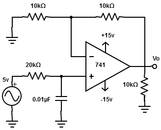
27. Using the frequency scaling technique, convert the 10kHz cut-off frequency of the low pass filter to a cutoff frequency of 16kHz.(Take C=0.01µF and R=15.9kΩ)
A. 6.25kΩ
B. 9.94kΩ
C. 16kΩ
d )1.59kΩ
Answer: B
To change a cut-off frequency from 10kHz to 16kHz, multiply the 15.9kΩ resistor.
However, 9.94kΩ is not a standard value. So, a potentiometer of 10kΩ is taken and adjusted to 9.94kΩ.
28. Find the difference in gain magnitude for a filter, if it is the response obtained for frequencies f1=200Hz and f2=3kHz. Specification: AF=2 and fH=1kHz.
A. 4.28 dB
B. 5.85 dB
C. 1.56 dB
D. None of the mentioned
Answer: C
When f1=200Hz, VO(1)/Vin =AF/√ [1+(f/fH)2]
=2/√ [1+(200/1kHz) 2] =2/1.0198.
=> VO(1)/Vin =1.96
=>20log|(VO/Vin)|=5.85dB.
When f=700Hz
VO(2)/Vin= 2/√ [1+(700/1kHz) 2]
=2/1.22=1.638.
=> VO(2)/Vin =20log|(VO/Vin|
=20log(1.638) = 4.28.
Therefore, the difference in the gain magnitude is given as
VO(1)/Vin-VO(2)/Vin
=5.85-4.28 =1.56 dB.
29. Design a low pass filter at a cut-off frequency 1.6Hz with a passband gain of 2.
10kΩ
9kΩ
8kΩ
6kΩ
Answer: A
From the answer, it is clear that all the C values are the same. Therefore,
c= 0.01µF
Given, fH = 1kHz,
=> R= 1/(2πCfm)
= 1/2π × 0.01µF × 1kHz
R= 9.9kΩ ≅ 10kΩ. Since the passband gain is 2.
=> 2=1+ (RF/R1). Therefore, RF and R1 must be equal.
30. How can a first-order low pass filter can be converted into a second-order low pass filter?
A. By adding LC network
B. By adding an RC network
C. By adding RC || LC network
D. None of the mentioned
Answer: B
By adding an RC network the first-order low pass filter can be converted into a second-order low pass filter.
The addition of the RC network makes the stopband response have a 40dB/decade.
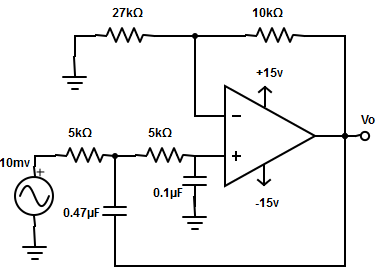
31. Consider the following specifications and calculate the high cut-off frequency for the circuit given?
A. 95Hz
B. 48Hz
C. 14Hz
D. 33Hz
Answer: D
The high cut-off frequency,
fH= 1/[2 π√(R2 × R3 × C2 × C3)]
= 1/[2π√(33kΩ × 15kΩ × 0.47µF × 0.1µF)]
= 1/[2π × 4.82 × (10-3)]= 33Hz.
32. Find the gain and phase angle of the second-order low pass filter?
Where the passband gain of the filter is 5, the frequency and the high cut-off frequency of the filter are 3000Hz and 1kHz.
A. None of the mentioned
B. Gain magnitude = -1.03dB , φ =63.32o
C. Gain magnitude = -5.19dB , φ =71.56o
D. Gain magnitude = -4.94dB , φ =90o
Answer: C
The gain of the second order low pass filter
[VO /Vin] =AF/ √ [1+(f/fh)2]
=5/ √[1+(3000/1000)4]
=5/9.055 =0.55.
=> [VO /Vin] = 20log(0.55) =-.519dB.
Phase angle of second order low pass filter is given as φ= tan-1(f/fH)
=> φ =71.56o.
33. A second-order low pass filter is given an input frequency of 30kHz and produces an output having a phase angle of 79o. Determine the passband gain of the filter?
A. 11 dB
B. 89.11 dB
C. 46.78 dB
D. None of the mentioned
Answer: C
Phase angle of the filter,
φ = tan-1(f/fH)
=> fh =f × tan(φ)
=30kHz × tan(79) = 154.34kHz.
Therefore, the pass band gain
AF = fH/0.707 = 154.34kHz/0.707
AF= 218.3 =20log(218.3)= 46.78dB.
34. The passband voltage gain of a second-order low pass Butterworth filter is
A. 1.586
B. 8.32
C. 0.586
D. 0.707
Answer: A
The second-order low pass filter has a passband voltage gain equal to 1.586 because of equal resistor and capacitor values. This gain is necessary to guarantee Butterworth’s response.
35. Arrange the series of steps involved in designing a filter for first-order low pass filter
Step 1: Select a value of C less than or equal to 1µF
Step 2: Choose a value of high cut-off frequency fH
Step 3: Select a value of R1C and RF depending on the desired passband gain
Step 4: Calculate the value of R
A. Steps- 2->4->3->1
B. Steps- 4->1->3->2
C. Steps- 2->1->4->3
D. Steps- 1->3->4->2
Answer: B
The series of steps involved in designing a filter for a first-order low pass filter is
Step 1: Calculate the value of R
Step 2: Select a value of C less than or equal to 1µF
Step 3: Select a value of R1C and RF depending on the desired passband gain
Step 4: Choose a value of high cut-off frequency fH
The mentioned option is the sequence of steps followed for designing a low pass filter.
36. Frequency scaling is done using
A. Standard capacitor
B. Varying capacitor
C. Standard resistance
D. None of the mentioned
Answer: A
In frequency scaling, standard capacitors are chosen, because for the non-standard value of the resistor, a potentiometer is used.
37. How are the higher-order filters formed?
A. By increasing resistors and capacitors in low pass filter
B. By decreasing resistors and capacitors in low pass filter
C. By interchanging resistors and capacitors in low pass filter
D. All of the mentioned
Answer: C
High pass filters are often formed by interchanging frequency determining resistors and capacitors in low pass filters. For example, a first-order high pass filter is formed from a first-order low pass filter by interchanging components R and C.
38. In a first-order high pass filter, frequencies higher than low cut-off frequencies are called
A. Stopband frequency
B. Passband frequency
C. Centre band frequency
D. None of the mentioned
Answer: B
The low cut-off frequency, fL is 0.707 times the passband gain voltage. Therefore, frequencies above fL are passband frequencies.
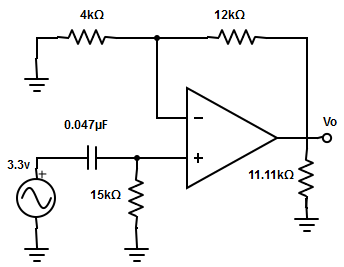
39. Compute the voltage gain for the following circuit with an input frequency 1.5kHz.
A. 4dB
B. 15dB
C. 6dB
D. 12dB
Answer: D
|VO/Vin|= [AF × (f/fL)]/ [√1+(f/fL)2]
= [4 × (1.5kHz/225.86)] / √[1+(1.5kHz/225.86)2]
=26.56/6.716=3.955
=20log(3.955)=11.9.
|VO/Vin|≅12 dB
AF= 1+(RF /R1)= 1+(12kΩ/4kΩ) =4.
fL= 1/(2πRC. = 1/2π × 15kΩ × 0.047µF
= 1/4.427 × 10-3 =225.86Hz.
40. Determine the expression for the output voltage of the first-order high pass filter?
A. VO = [1+(RF /R1)] × [(j2πfRC/(1+j2πfRC.] × Vin
B. VO = [-(RF /R1)] × [(j2πfRC/(1+j2πfRC.] × Vin
C. VO = {[1+(RF /R1)] × /[1+j2πfRC] } × Vin
D. None of the mentioned
Answer: A
The first-order high pass filter uses a non-inverting amplifier.