The braking torque of induction type single-phase energy meter is
Right Answer is:
Directly proportional to the square of the flux
SOLUTION
The braking torque of the induction type single-phase energy meter is directly proportional to the square of the flux.
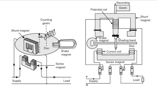
Induction-type Single-phase Energy Meter
An induction-type instrument can be used as an ammeter, voltmeter, or wattmeter. Induction-type single-phase energy meter is used invariably to measure the energy consumed in an AC circuit in a prescribed period where supply voltage and frequency are constant. The energy meter is an integrating instrument that measures the total quantity of electrical energy supplied to the circuit in a given period.
A single-phase energy meter has four essential parts:
- Operating system
- Moving system
- Braking system
- Registering system
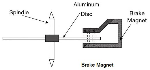
Braking System
The braking system consists of a braking device which is usually a permanent magnet positioned near the edge of the aluminum disc. The arrangement is shown in Figure.
The emf induced in the aluminum disc due to relative motion between the rotating disc and the fixed permanent magnet (brake magnet) induces an eddy current in the disc.
When the disc rotates in the air gap, eddy currents are induced in the disc which opposes the cause producing them i.e. relative motion of the disc with respect to the magnet. This eddy current, while interacting with the brake magnet flux, produces a retarding or braking torque. This braking torque is proportional to the speed of the rotating disc. When the braking torque becomes equal to the operating torque, the disc rotates at a steady speed.
The braking torque is proportional to the flux of the braking magnet and the eddy current induced in the moving system due to its rotation in the field of the braking magnet.
TB ∝ φi
where φ is the flux of the braking magnet and ‘i’ the induced current. Now i = e/R where e is the induced e.m.f. and R the resistance of the eddy current path. Also, e ∝ φn where n is the speed of the moving part of the instrument.
∴ TB ∝ φ × φn/R
TB ∝ φ2n/R
The position of the permanent magnet with respect to the rotating disc is adjustable. Therefore, braking torque can be adjusted by shifting the permanent magnet to different radial positions with respect to the disc. By changing the distance between braking magnet and magnetic shunt, the braking torque can be adjusted. The braking torque increases when the distance between them is increased because of moving the magnetic shunt away from the magnet, it will bypass a less amount of flux and vice versa.
Hence the Braking torque provided by a permanent magnet is proportional to
- Square of the flux of the permanent magnet
- The speed of the meter
- The distance of the permanent magnet from the center of the revolving disc