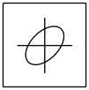
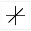
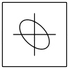
1. Horizontal input to a scope is Emsin(ωt) V, vertical input to that scope is Emsin(ωt + 30°) V. What is the Lissajous pattern in that CRO?
A.
B.
C.
D.
Answer.1.
Explanation:
When two sinusoidal signals of the same frequency and magnitude are applied two both pairs of deflecting plates of CRO, the Lissajous pattern changes with the change of phase difference between signals applied to the CRO
When 0 < ϕ < 90° or 270° < ϕ < 360°
The Lissajous pattern is of the shape of an Ellipse having a major axis passing through the origin from the first quadrant to the third quadrant.
When 90° < ø < 180° or 180° < ø < 270°
The Lissajous Pattern is of the shape of an Ellipse having a major axis passing through the origin from the second quadrant to the fourth quadrant.
Explanation:
The given inputs are: Emsin(ωt) V, Em sin (ωt + 30°) V
The phase difference between both the inputs = 30°
The Lissajous pattern on the screen of a CRO is an ellipse with a major axis in quadrant 1 and quadrant 3.
2. CRO stands for __________
Cathode Ray Oscilloscope
Current Resistance Oscillator
Central Resistance Oscillator
Capacitance Resistance Oscilloscope
Answer.1. Cathode Ray Oscilloscope
Explanation:
The cathode-ray oscilloscope (CRO) is a common laboratory instrument that provides accurate time and amplitude measurements of voltage signals over a wide range of frequencies.
3. Aquadag coating is most commonly used in CROs to:
Absorb moisture
Absorb the extra electrons emitted
Absorb and emit the rays
Absorb the rays emitted
Answer.2. Absorb the extra electrons emitted
Explanation:
Aquadag is the name of a water-based colloidal graphite coating which is a colloidal solution of graphite in water.
The bombarding electrons, striking the screen, release secondary emission electrons
These secondary electrons are collected by an aqueous solution of graphite called Aquadag which is connected to the second anode
It is the conductive coating on the screen
Collection of secondary electrons is necessary to keep the CRT screen in a state of electrical equilibrium
The Aquadag coating also shields the interior of the tube from external electric and magnetic fields, preventing those from affecting the path of the electrons.
4. A C.R.O gives _______
Actual representation
Visual representation
Approximate representation
Incorrect representation
Answer.2. Visual representation
Explanation:
The C.R.O. gives the visual representation of the time-varying signals.
In studying the various electrical and electronic systems, signals which are functions of time are often encountered. Such signals may be periodic or non-periodic in nature. The device which allows the amplitude of such signals to be displayed primarily as a function of time is called Cathode Ray Oscilloscope is commonly known as C.R.O.
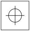
5. Two equal voltage of same frequency applied to the X and Y plates of a CRO, produce a circle on the screen. The phase difference between the two voltages is
30°
60°
90°
150°
Answer.3. 90°
Explanation:
In CRO we can measure the phase difference by X-Y mode operation.
At a phase shift ϕ = 0° or 360°, the pattern indicated by CRO is a diagonal straight line making 45° with the X-axis.
At a phase shift of ϕ = 90°, the pattern indicated by CRO is a clockwise rotating circle.
At phase shift ϕ = 180°, the pattern indicated by CRO is a diagonal straight line making 135° with the X-axis.
At phase shift ϕ = 270°, the pattern indicated by CRO is an anti-clockwise rotating circle.
6. A Oscilloscope is ________
An ohmmeter
An ammeter
A voltmeter
A multimeter
Answer.3. A Voltmeter
Explanation:
The oscilloscope is basically an electron beam voltmeter. The heart of the oscilloscope is the Cathode Ray Tube (CRT) which makes the applied signal visible by the deflection of a thin beam of electrons.
If the oscilloscope is a Cathode Ray Oscilloscope (CRO) it can be considered as a voltmeter. This can be used to measure the potential differences between the two points.
7. In an oscilloscope, the sensitivity can be increased by _________
Decreasing the value of accelerating voltage Ea
Increasing the value of accelerating voltage Ea
Increasing the separation between the deflecting plates
None of these
Answer.1. Decreasing the value of accelerating voltage Ea
Explanation:
The deflection sensitivity of a CRO is defined as the vertical deflection of the beam on the screen per unit deflecting voltage. It is also defined as the deflection produced per volt of deflecting voltage. Therefore, the unit of deflection sensitivity of the CRO is – meter per volt (m⋅V−1).
Deflection sensitivity S = D/Ed = LId/2dEa
Where D = deflection of an electron beam on the screen in the Y direction in m
Ed = potential between deflecting plates in V
L = distance between the screen and the center of the deflecting plates in m
ld = length of the deflecting plates in m
d = distance between deflecting plates in m
Ea = accelerating voltage in V
Therefore S ∝ 1/Ea
Hence In an oscilloscope, the sensitivity can be increased by Decreasing the value of accelerating voltage Ea
8. The Electron beam from Cathode Ray tube is deflected in __________
1 direction
4 directions
3 directions
2 directions
Answer.4. 2 directions
Explanation:
The electron beam in an oscilloscope can be deflected in two directions, namely the horizontal (x-direction) and the vertical (y-direction).
After the electrons leave the electron gun assembly, they pass through a region controlled by the deflection plates. The deflecting system consists of a pair of horizontal deflecting plates (X-set) and a pair of vertical deflecting plates (Y-set) placed at right angles to each other.
A positive voltage applied to the X-plates will deflect the beam towards the right (+ x-axis) while a negative voltage applied to the X-plates will deflect the beam towards the left (- x-axis).
Similarly, a positive voltage applied to the Y-plates causes the beam to deflect vertically upwards (+ y-axis) due to the attraction forces, while a negative voltage applied to the Y-plates cause the beam to deflect vertically downwards (- y-axis) due to the repulsion forces.
The amount of deflection is directly proportional to the potential across the plates. If the voltages are applied simultaneously to X- and Y-plates, the electron beam is deflected due to the resultant of these voltages.
When no voltage is applied across the plates X and Y, the beam passes between them undeflected and produces a bright spot at the center of the screen.
9. The purpose of synchronizing control in a CRO is to:
Focus the spot on the screen
Lock the display of the signal
Adjust the amplitude of display
Control the intensity of spot
Answer.2. Lock the display of the signal
Explanation:
CRO is a very fast X-Y plotter that shows the input signal versus another signal or versus time.
Intensity control is used to adjust the brightness of the waveform. As the sweep speed is increased, there is a need to increase the intensity level.
Focus control is used to adjust the sharpness of the waveform
A trace control is used to rotate the trace on the CRO screen
Synchronizing control is used to lock the display of the signal
10. CRO is a ________
Fast x-y plotter
Slow x-y plotter
Medium x-y plotter
Not a plotter
Answer.1. Fast x-y plotter
Explanation:
CRO is a very fast X-Y plotter that shows the input signal versus another signal or versus time.
Intensity control is used to adjust the brightness of the waveform. As the sweep speed is increased, there is a need to increase the intensity level.
Focus control is used to adjust the sharpness of the waveform
A trace control is used to rotate the trace on the CRO screen