
Construction of Alternator
- The AC generator (alternator) or synchronous generator is a machine which converts the mechanical power or energy into electrical power.
- The construction of an alternator is very similar to the DC generator but the main difference between them in DC generator the armature winding is the rotating part and field winding is the stationary part whereas in an alternator the armature winding is stationary and field winding is the rotary part.
Stator
- As the name suggests it is the stationary part of the machine and it is made up of special magnetic material which can allow high magnetic permeability and low magnetic hysteresis such as fabricated steel.
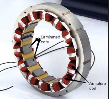
- The stator core is laminated to minimize the effect of eddy current losses.The lamination is insulated from each other by a thin coating of an oxide and has space between them to allow passage of cool air flow.
- For the small machine, the laminations are stamped out in the complete ring structure and for the large machine, the laminations are divided into the number of segments.
- The slots are provided in the inner periphery of the core and the armature conductors or coils are assembled in it.
- Generally, open slots are used permitting easy installation or removal of the stator coil.
- The fractional number of slots per pole is used in order to eliminate the harmonic in the waveform.
- The armature winding of an alternator is usually connected in star and its neutral is connected to the ground.
Why is the Armature winding of an Alternator connected in Star?
- The phase voltages in star connection are 57.7 % of the line voltages, i.e. the armature winding in star connection is less exposed to voltage as compared to the delta connection which in turn prove more economic if we consider insulation, breakdown strength, the requirement of conductor material etc.
- In star connection, if the neutral is grounded then it also provides a path for the Zero-Sequence currents during faults, whereas in the delta connection the zero sequence currents flow within the delta circuit and hence increasing the load on the winding.
Rotor
- The revolving field structure of the electrical machine is called as the rotor. In a synchronous generator, the rotor carries a field winding which is supplied by the DC source.
- The DC source is also called an exciter which is generally a small d.c shunt or compounded generator mounted on the shaft of the alternator.
There are two types of rotor construction
- Salient Pole Type
- Cylindrical Type (non-salient pole)
Salient (or projecting Pole) Type
- The salient pole type rotor is used for low and medium speed machines (less than 1200 rpm) and have the large diameter and small axial length.
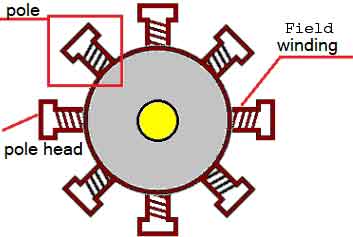
- The poles are made up of thick steel lamination to reduce eddy current heating loss and it is attached to a rotor by means of the dovetail joint.
- In salient pole rotor, the poles are always projected in the outward direction as shown in the figure.
- The field winding in the salient pole type is connected in series in such a way that when the field winding is energised by the exciter, then adjacent poles will have opposite polarities. The number of poles does not affect the number of phases in the alternator output.
- To reduce the effect of haunting damper winding is provided in the pole faces. They don’t let the motor to oscillate abruptly, they damp the oscillations thus increasing the stability of the machine.
- Salient pole rotor found application for diesel engine and water turbine because they both required medium speed (120-1000 rpm).
- The pole and Pole shoe cover 2/3 of the pole pitch.
- The rating of salient pole rotor is less than 500 kW.
Disadvantage of Salient Pole Rotor
The salient pole rotor has following disadvantages
- The salient pole rotor cause excessive windage looses if they are driven at high speed and it also increases the noise produced by an alternator.
- The construction of salient pole rotor cannot withstand high mechanical stress.
- The speed of an alternator is inversely proportional to the numbers of pole required (Ns = 120f/p) so to operate a salient pole type alternator, a large number of poles are required which increases the diameter of the generator thus increasing space requirement for installation and initial cost due to extra material used.
Smooth Cylindrical Type | Non-Salient Pole Alternator
- This type of Rotor is used for steam driven alternator i.e turbo alternator which runs at very high speed.

- The Rotor is made up of smooth solid forgings of alloy steel cylinder having the number of slots along the outer periphery.
- The field windings of cylindrical type rotor are connected in series to the slip rings through which they are excited by the DC exciter.
- The top portion of the slot is covered with the help of steel or manganese wedges and the unslotted portion of the cylinder acts as the poles of an alternator.
- The field windings are arranged in such a way that its flux density is maximum on the polar central line.
- In cylindrical rotor, the pole doesn’t project out from the smooth surface of the rotor hence they maintain the uniform air gap between stator and rotor.
- Since steam turbine runs at very high speed, therefore, they required less number of poles hence the diameter of the rotor is small and axial or rotor length is large.
Advantages of Cylindrical Rotor type Alternator
- The main advantages of the cylindrical rotor are that their construction has mechanical robustness and gives noiseless operation at very high speed (1500-3000 rpm).
- The flux distribution is nearly uniform sine wave hence better waveform is obtained.
- The hunting effect is very rare in the cylindrical rotor, therefore, there is no need to provide damper winding except in case of assisting the alternator for synchronising purpose.
Types Of Alternator
The alternator can be divided into different types based on their application, prime mover, design, output power, and cooling.
Alternator Based on their Output Power
- Single Phase Alternator
- Two-Phase Alternator
- Three Phase Alternator
Single Phase Alternator
The single phase alternator produces a continuous single alternating voltage. The armature coils are connected in series forming a Single circuit in which output voltage is generated.
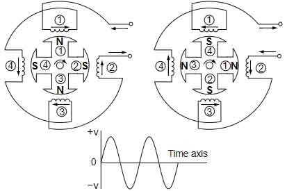
In the above figure, the stator has four poles which are evenly spaced around the stator frame. The rotor also consists 4 poles and each pole has opposite polarity to its neighbours which are angled at 90 degrees. Each coil also has opposite winding to its neighbours. This configuration allows the lines of force at 4 poles to be cut by 4 coils at the same amount at a given time. At each 90-degree rotation, the voltage output polarity is switched from one direction to the other. Therefore, there are 4 cycles of the AC output in one rotation.
Single-phase generators are used as standby generators in case of the main power supply is interrupted and for supplying temporary power on construction sites.
Two-Phase Alternator
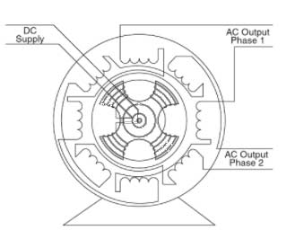
In a two-phase alternator, there are two single-phase windings spaced physically so that the ac voltage induced in one is 90° out of phase with the voltage induced in the other. The windings are electrically separate from each other. Suppose in the first quarter first winding produce maximum flux, then the second winding generates zero flux and in the second quarter the second winding generates maximum flux and first winding generate zero flux. This condition establishes a 90° relation between the two phases.
Three Phase Alternator
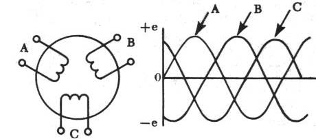
A three-phase alternator has 3 sets of single-phase windings arrangement so that the voltage induced in each winding is 120° out of phase with the voltages in the other two windings. These windings are connected in the star to provide a three-phase output.
Advantages of Three-phase Alternator
- The three-phase alternator gives the most constant output than the single phase alternator.
- Three phase power supply is more economical than the other two phases because three separate single-phase voltage can be delivered at the same time from the power system.
Alternator based on their applications
According to their application usage, the alternator can be divided into 5 main part.
- Automotive Type Alternator
- Diseal electric locomotive Alternator
- Brushless type Alternator
- Marine Type Alternator
- Radio Alternator
Alternator based on their Prime-mover
- Turbo Generator
- Hydro Generator
- Diseal Engine driven Alternator
Alternator Based on Type of their Design
- Salient pole Rotor
- Smooth cylindrical Rotor