
Contactors and relays are misinterpreted most of the time as they both are closely related terms leading to confusion. A relay is basically just an electrically operated switch. Some are tiny and handle only small amounts of current at low voltages, whereas other types, called contactors, are huge (the size of a small refrigerator) and can safely deal with hundreds of amperes and thousands of volts. But regardless of size and power capacity, all relays and their close cousins the contactors use the same basic principle of operation.
Principle of Operation of Relay and Contactor
Relays and contactors are electromechanical switches. They operate on the solenoid principle. A coil of wire is connected to an electric current, The magnetic field developed by the current is concentrated in an iron pole piece. The electromagnet attracts a metal armature. Contacts are connected to the metal armature. When the coil is energized, the contacts open or close. There are two basic methods of constructing a relay or contactor. The clapper type uses one movable contact to make the connection with stationary contact. The bridge type uses a movable contact to make the connection between two stationary contacts.
Electrical control relay
The electrical control relay is an electromechanical device that contains auxiliary contacts. Auxiliary contacts are small and are intended to be used for control applications. As a general rule, they are not intended to control large amounts of current. Current ratings for most relays can vary from 1 to 10 amperes depending on the manufacturer and type of relay. The major parts of a relay are shown in the simplified diagram of Figure. Essentially, the relay consists of a:
⇒ Coil, designed to operate at a specific voltage, and if a.c. a specific frequency.
⇒ Magnetic circuit, part of which is a moving plunger or armature.
⇒ Set of spring-loaded contacts, some of which may be normally open (NO) contacts while others may be normally dosed (NC).
⇒ The mechanical linkage between the plunger/armature and the contacts.
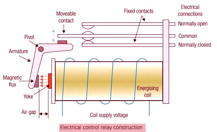
- When the relay coil is energized, the magnetic flux produced attracts the armature to the soft-iron core of the coil. When this occurs, the armature moves about its pivot point and causes the contacts to change state.
- When the coil is de-energized, the magnetic flux is no longer present and a spring returns the armature and contacts to what is known as their normal state. As a result of this operation, the contacts of a relay are referred to as either normally open (NO) or normally closed (NC).
- The term ‘normal’ relates to the conditions when the relay coil is de-energized. The operation of the relay and its contacts can be summarised using the following terms:
⇒ De-energized: No voltage is applied to the relay coil.
⇒ Energized: Rated voltage is applied to the relay coil.
⇒ Normally open: NO contacts are open when the relay coil is de-energized and closed when the relay coil is energized.
⇒ Normally dosed: NC contacts are dosed when the relay coil is de-energized and open when the relay coil is energized.
Contactor
The contactor is a larger version of the relay. Devices switching more than 15 amperes or in circuits rated more than a few kilowatts are usually called contactors. A contactor is a mechanical switching device that is capable of making, carrying, and breaking electric current under normal circuit conditions including operating overload conditions. The contractor has the same basic construction as a relay. It is an electromechanical device that has an operating coil, a magnetic circuit, and one or more sets of contacts.
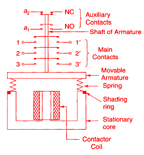
A contactor consists of an electromagnet and a movable core, called the armature. A set of contacts (main contacts and auxiliary contacts) is mounted on the armature’s shaft. The main contacts are heavy-duty contacts with high current carrying capacity. They are normally open (NO) contacts. There are three main contacts.
Power contacts are used for load switching and can have current-carrying capacities in the range of 8 A through to 2700 A. In addition, there are small contacts of normally 2A current rating. They are called auxiliary contacts. The auxiliary contacts can be added to either side or both sides of the contactor. Auxiliary contacts can have both NO contacts and NC contacts.
Main contacts are used in the power circuit, i.e., to supply power to the motor. The auxiliary contacts are used in the pilot circuit i.e. the control circuit. The figure shows the sectional view of an electromagnetic type contactor. It has three main contacts and two auxiliary contacts.
Contactor coil may have voltage rating like 24V, 230 V, 415 V. The main contacts have a rating in terms of their current carrying capacity. Auxiliary contacts are normally rated for low current, say 2A to 6A. When the contactor coil is energized, the armature gets attracted towards the stationary core against the spring pressure.
All its NO contacts are close and all its NC contacts open. When the coil is de-energized, the armature returns to its original position due to spring pressure. While specifying a contactor, we have to write the coil voltage rating, the current carrying capacity of the main contacts, and the combination of auxiliary contacts. A typical specification will be like this:
Specifications of a Contactor:
Main contacts: No. of contacts = 3
Nominal rating = 32 A at 415 V, 50 Hz.
Auxiliary contacts: No. of contacts = 2 NO + 2 NC
Rating at 415 V, 6 A, 50 Hz
Figure shows an exploded view of a contactor. The contacts may be NO, NC, or a combination of both. The major difference between a relay and a contactor is the current rating of the contacts. Relays have contacts that have low current-carrying capacities, whereas contractors have contacts that are capable of switching much higher currents. The important design features of contactors are listed below.
- The most compact in size and light in weight.
- A large number of contacts with high switching capacity.
- ‘Snap-fit’ arrangement of various parts.
- ‘Push-on’ type contacts for quick modification/replacement at the site.
- Very high endurance for the high frequency of operations.
Contactor VS Relay
1. Power Source Compatibility
Both RELAY and CONTACTOR can work on AC or DC power sources. Both AC and DC relay or contactor work on the same principle as that of electromagnetic induction, but the construction is somewhat differentiated and also depends on the application for which these relays are selected. DC relay or contactor generally contains solid core materials and is employed with a freewheeling diode to de-energize the coil, whereas those intended for use with alternating current.
The construction of the electromagnetic part of a relay or contactor greatly depends on whether it is to be operated by direct or alternating current. Relays and contactors that are operated by direct current generally contain solid core materials, whereas those intended for use with alternating current contain laminated cores. The main reason for the laminated core is the core losses associated with alternating current caused by the continuous changing of the electromagnetic field.
2. Load Capacity
Most relay coils are intended to operate on voltages that range from 5 to 120 volts AC or DC. Contactors can be obtained with coils that have voltage ranges from 24 to 600 volts. Although these higher voltage coils are available, most contactors operate on voltages that generally do not exceed 120 volts for safety reasons.
Relays have contacts that have low current-carrying capacities around 1-10 A, whereas contactors have contacts that are capable of switching much higher currents around 10 to 2700 A.
3. Open/Closed Contact Standards
Relays often contain more than one set of contacts or switches. Relay contacts are always shown as normally open (NO) or normally closed (NC) with the coil in the de-energized position. Energizing the coil causes the contacts to change position. Some relays have both normally open and normally closed contacts, and many relays have multiple sets of contacts. Contactors typically have multiple sets of normally open contacts. contactors are exclusively designed to operate with normally open contacts.
Since the contactors have heavy-duty contacts for controlling larger loads. These contacts are normally open (NO) and controlled by a magnetic coil. When the coil is energized, the contacts close. Contacts are used to open or close a circuit between the main power supply and the load and are rated according to the maximum amperage flow through the contacts for a specific voltage. A two-pole contactor has two separate contacts and is used to control 240-volt single-phase circuits (for residential air conditioning). A three-pole contactor has three sets of contacts and is used to control three-phase loads (for commercial and industrial).
4. Auxiliary Contacts
The basic difference between a contactor and a relay is that a contactor has three or four main contacts and few auxiliary contacts whereas a relay have only auxiliary contacts. Relay consists of at least two NO/NC contacts. A contactor is used in the power circuit whereas a relay is used in the control circuit, i.e., the pilot circuit.
5. Safety Features (Spring-Loaded Contacts)
Spring-loaded contacts contain a return spring. The spring returns the plunger to the starting position following the de-energization of the coil. These devices require continuous energization to maintain the plunger in the operating position.
Since contactors are used for high power applications, they often contain additional safety features such as spring-loaded contacts to ensure the circuit is broken when de-energized.
Latching: This means that the contactor switch is not spring-loaded, and it stays in whatever position it is placed into until the polarity is reversed to the coil, which returns the contactor switch to its original position. This is comparable to a standard home light switch—it stays on until you turn it off.
Non-latching: This is the “normal” type of contactor that we use for failsafe switches. The relay contactor switch is spring-loaded and returns to the preset position unless power is applied to the coil. This is comparable to a momentary button switch—it stays on only while you press the button; otherwise, it springs back to the off position.
Once activated, contactors are either mechanically or electrically held in the closed position. In the mechanically held contactor, the mechanism closes when the coil is activated, and it is held closed by a mechanical ‘latch’ until a second coil is activated, which `unlatches’ the mechanism. This requires only a momentary application of coil power through the switching device.
The electrically held contactor requires that coil power be continuously applied while the contactor is closed. Removal of coil power allows the spring-loaded contactor to open. The electrically held contactor is less expensive than the mechanically held, but it can produce an undesirable buzzing sound while the coil is energized.
Since relays are typically for lower power, spring-loaded contacts are much less common.
6. Safety Features (Arc Suppression)
The contactor is a large relay. Contactors control high-energy circuits involved with lighting, heating elements, magnetic brakes, and overload protection, motors, and machinery. They contain mechanisms to break the contact rapidly following the de-energization of the electromagnet. Similarly, the movement of the plunger in the relay is also rapid.
The purpose of the rapid disconnection is to break the arc that establishes between the contacts during separation. This arc is responsible for the arc flash and arc blast that occur in electrical equipment. Note that these arcs can develop when the contactor opens under load. This is similar in concept to the arc created during welding during the controlled separation of the electrode from the base metal. Some units contain arc-entrapment devices to minimize the impact of this situation.
Since relays are designed for light load application therefore arcing is less of a concern, and arc suppression is much less common on relays.
7. Safety Features (Overloads/Line starter/Motor Starter)
Motor starters/Line starters are contactors with the addition of an overload relay.
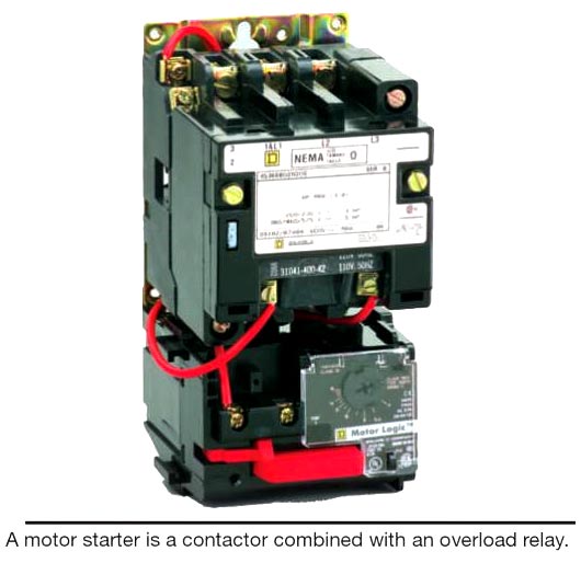
Line starters are often used to operate and protect three-phase motors. Overloads protect the motor against excess amperage and are more accurate than fuses. Overload protectors are normally connected to the bottom of the contactor and sized to the amperage of the motor. One overload is required for a single-phase power supply to the motor. For a three-phase line starter, there must be at least two overloads. Supply voltage must flow through heavy-duty contacts and then through the overload heater before traveling to the motor.
Overloads are much less common on relays.
Contactor VS Relay Selection
Relay selection
The correct selection of a control relay for a specific application is dependent upon several factors. These are
⇒ The voltage, frequency, and type of supply (A.C or D.C) from which the coil is to be supplied. Typical voltage ratings include: 24, 32, 48, 110, 230 and 400 V at 50 Hz and d.c. 12, 24, 32, 48, and 110 V.
⇒ The number and type of contacts required; that is, how many NO and how many NC contacts does the application require? Note, in most relays the NC contacts open before the NO contacts close. This is known as a break before make contacts’. To achieve correct sequencing of circuit operation, some applications require the exact opposite; that is, ‘make before break contacts. In this case, the NO contacts close before the NC contacts open.
⇒ The current rating of the relay contacts must be equal to or greater than the full-load current of the device to be switched. Additionally, the type of load (resistive, inductive, or capacitive) to be switched must be taken into account. This is known as the ‘utilization category of the relay.
⇒ The physical site of the relay. If the space available for the installation of the control circuit is limited, a relay of compact size must be selected.
⇒ The type of mounting for the relay may have to be considered. Mounting styles include surface mounting, plug-in base, and DIN rail mounting.
Contactor selection
⇒ The main factors to be considered when selecting a contactor are very similar to those for a relay and other control devices. Specifically, the factors to be considered when selecting a contactor are:
⇒ The voltage and frequency rating of the contactor coil must be correct; for example, 400 V, 50 Hz
⇒ The number of poles, the current carrying capacity and voltage rating of the power contacts must be equal to or above the full-load current of the load
⇒ The utilization category of the contactor must be suitable for the application (also called the category of duty).
⇒ The number, type, and current rating of the auxiliary contacts must be appropriate for the application.
⇒ Type of contactor mounting.
Contactor vs Relay Applications
The distinction between Contactor vs Relay applications usually is based on the amount of electricity the switch is designed to handle; relays are normally used in low-power applications or single-phase circuits and contactors are used in high-power circuits. (both single-phase and three-phase circuit).
Relays are useful for routing signals, switching current, or as a form of logic for some applications. While is it possible to use a solid-state component to do switching and routing chores, the relay offers the advantage of low closed-circuit resistance, immunity to reverse current flow from inductive loads, and the ability to act as an isolated control transition between low- and high-voltage circuits.
Contactors are devices specially designed for motor control duty, available in two poles versions for DC and three and four poles versions for AC applications, electric motor control, switching electric heating elements, and large banks of lights.
Contactor VS Relay failure
Relays can fail for three main reasons:
⇒ Open circuit (break) or high resistance in the relay coil wiring or connections resulting in little or zero current flow through the coil. This prevents the relay from energizing. This failure causes electrical devices supplied with electricity through the normally open contacts of a relay not to operate.
⇒ Relay contacts are burned or otherwise damaged, resulting in a high level of series resistance with the load device when the contacts are closed. This can cause low or zero current flow through the closed relay contacts. This failure also causes electrical devices that are supplied current through the normally open contacts of a relay not to operate or to operate erratically.
⇒ Relay normally open contacts are welded or stuck in the closed (energized) position. This causes the normally open contacts to remain closed even after the relay coil is no longer energized and causes the normally closed contacts to remain open at all times with SPDT relays. This problem often occurs due to the relay conducting too much current or switching too high a voltage. This failure causes electrical devices that are supplied current through the normally open contacts of a relay to operate when the relay coil is not energized.
The main reason for contactor failure is high current, electrodynamic forces during a short circuit, overvoltage, continual chattering, aging temperature, power quality, Corrosive environment, voltage and frequency fluctuation, and mechanical shock.
⇒ High current can be either due to overload or due to short-circuit. High current can cause the contacts to melt.
⇒ Continual chattering also melts the contacts.
⇒ Aging causes the coils inside the contactor to crack which causes the insulation to break.
⇒ Chemicals and vapors in the surrounding environment cause damage to the contactor coil. At present, testing of these contactors is done manually.
⇒ The electrodynamic forces during a short circuit can mechanically damage the contactor.
⇒ Overvoltage causes a high current to flow in the coil damaging it.
Summary contactor vs relay
S.No |
Criteria |
Relay |
Contactor |
1 |
Power Source Compatibility |
Work on both A.C & D.C. Used for single |
Work on both A.C & D.C |
2 |
Device Size |
It is smaller in size |
It is comparatively larger in size |
3 |
Current Switching Capacity |
Used for low current-carrying capacities around 1-10 A. |
Used for higher current application of around 10 to 2700 A. |
4 |
Auxiliary Contacts |
Relay has only auxiliary contacts (at least two NO/NC contacts) |
Contactor has three or four main contacts and few auxiliary contacts |
5 |
Safety features |
It is used for low power application hence inbuilt safety features for the relay is less common. |
Used for high power application therefore additional safety features are provided such as Spring-Load, Arc suppression, overload, |
6 |
Open/Closed Contact Standards |
Some relays have both normally open and normally closed contacts, and many relays have multiple sets of contacts. |
Contactors typically have multiple sets of normally open contacts. They are exclusively designed to operate with normally open contacts. |
7 |
Voltage Capacity |
They operate on voltages that range from 5 to 120 volts AC or DC |
Contactors can be obtained with coils that have voltage ranges from 24 to 600 volts. |
8 |
Application |
Routing signals, switching current, control circuits, or as a form of logic for some applications. Used for low-power applications. |
Motor control duty, electric motor control, switching electric heating elements, and large banks of lights. Used for high power applications. |
9 |
Cause of failure |
Open circuit (break) or high resistance, contacts burned, contacts welded or stuck in the closed (energized) position. |
High current, electrodynamic forces during a short circuit, overvoltage, continual chattering, aging temperature, power quality, Corrosive environment, voltage and frequency fluctuation, and mechanical shock. |