
Ques 61. In a control system, the output of the controller is given to
- Final control element
- Amplifier
- Comparator
- Sensor
Explanation:
Element of control element
Input: The applied signal or excitation signal applied to a control system from an external source in order to produce output is called input.
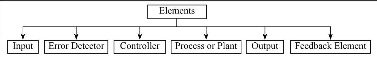
Error Detector: The error detector is used to reduce the error signal. The error signal is the difference between the input signal and the feedback signal. It is used to reduce the error and bring the output of the system to the desired value.
Controller: The element of the control system which controls the process or plant is called the controller.
Process or Plant: It is defined as the portion of a system that is to be controlled or regulated. It is also called process. Output: The actual response obtained from a control system when the input signal is applied to it is called output.
Feedback Element: The device which is used to give the feedback signal is called the feedback element. The feedback is a property of the system by which it permits the output to be compared with the reference input to generate the error signal based on which the appropriate controlling action can be decided. The purpose of feedback is to reduce the error between the reference input and the system output.
The correction element or final control element is the element in a control system that is responsible for transforming the output of a controller into a change in the process which aims to correct the change in the controlled variable. Thus, for example, a switch which is operated by the controller and so used to switch on a heater to control.
The final control element comes in a variety of forms depending on the specific control application. In chemical engineering processes, the final control element is an automatic control valve that throttles the flow of a manipulated variable. In mechanical engineering systems, the final control element is a hydraulic actuator or an electric servomotor.
Ques 62. In an automatic control system which of the following elements is not used?
- Error detector
- Final control element
- Sensor
- Oscillator
Explanation:
Element of control element
Input: The applied signal or excitation signal applied to a control system from an external source in order to produce output is called input.
Error Detector: The error detector is used to reduce the error signal. The error signal is the difference between the input signal and the feedback signal. It is used to reduce the error and bring the output of the system to the desired value.
Controller: The element of the control system which controls the process or plant is called the controller.
Process or Plant: It is defined as the portion of a system that is to be controlled or regulated. It is also called process. Output: The actual response obtained from a control system when the input signal is applied to it is called output.
Feedback Element: The device which is used to give the feedback signal is called the feedback element. The feedback is a property of the system by which it permits the output to be compared with the reference input to generate the error signal based on which the appropriate controlling action can be decided. The purpose of feedback is to reduce the error between the reference input and the system output.
The correction element or final control element is the element in a control system that is responsible for transforming the output of a controller into a change in the process which aims to correct the change in the controlled variable. Thus, for example, a switch which is operated by the controller and so used to switch on a heater to control.
The final control element comes in a variety of forms depending on the specific control application. In chemical engineering processes, the final control element is an automatic control valve that throttles the flow of a manipulated variable. In mechanical engineering systems, the final control element is a hydraulic actuator or an electric servomotor.
In control system engineering our main is to make the system stable, accurate, and free from error and the presence of oscillator make our system highly unstable hence the oscillator is not used in an automatic control system.
Ques 63. A controller essentially is a
- Sensor
- Clipper
- Comparator
- Amplifier
Explanation:
Element of control element
Input: The applied signal or excitation signal applied to a control system from an external source in order to produce output is called input.
Error detector or comparator: It is a device where the reference input and feedback signal are compared, and if there is a difference, an error signal is generated. Error signal:
Controller: Controller is a device whose input is the error signal and the output is the actuating signal. It acts to reduce the error to zero by making the actual output equal to the desired output. The controller essentially is a comparator.
The controller is an element that accepts the error in some form and decides the proper corrective action. The output of the controller is then applied to the process or final control element. This brings the output back to its desired setpoint value.
A control system is used to maintain its output within desirable limits by means of a control action or controller. Any deviation of the output from the reference input is detected by an error detector. The error is detected by an actuating signal for control action through a controller. The controller is used to improve the transient and steady-state response of a control system. So we can define a controller as follows. “A controller is a device which is used to get the desired objective as per requirement.
Ques 64. Which of the following is the input to a controller?
- Servo signal
- Desired variable value
- Error signal
- Sensed signal
Explanation:
Closed-Loop Control
- A closed-loop control system utilizes a measure of the actual output to compare the actual output with the desired output response.
- The measure of the output is called the feedback signal. The elements of a general closed-loop feedback control system are shown in Figure.
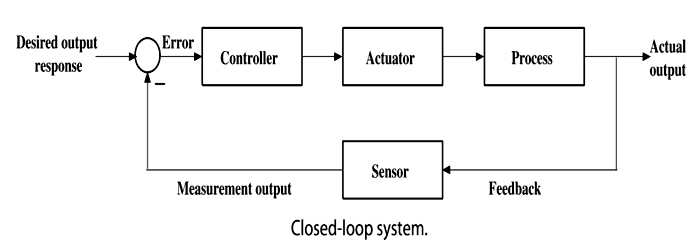
- A closed-loop control system compares the measurement of the output with the desired output (reference or command input).
- The difference between the two quantities (the error signal) is then used to drive the output closer to the reference input through the controller and actuator. Here the input signal to the controller is an error signal
- Often the difference between the output of the process under control and the reference input is amplified and used to control the process so that the difference is continually reduced.
Ques 65. The on-off controller is a _____ system.
- Digital
- Linear
- Non-linear
- Discontinuous
Explanation:
The controllers are basically classified as discontinuous controllers and continuous controllers.
The discontinuous mode controllers are further classified as ON-OFF controllers and multiposition controllers.
Two Position Mode(ON-OFF Controller)
- The two-position controller is also known as the ON-OFF controller.
- This type of controller is simple and inexpensive and are generally employed for home heating system, domestic water heaters, and industrial control system.
- For example, if the controlled process variable is room temperature, the switch would turn ‘ON’ the air cooler when the temperature is high and turn it “OFF° when the desired comfort level is reached.
- Thus, an ON-OFF controller operates on the manipulated variable only, when the temperature crosses the setpoint. The output has only two states, completely ON or completely OFF.
- The one stage is used when the temperature is above the desired value (setpoint) and the other state is used when the temperature is below the set point.
- The on-off controller is discontinuous at the point when the system changes its state from on to off.
Ques 66. The capacitance, in force-current analogy, is analogous to
- Momentum
- Velocity
- Displacement
- Mass
Explanation:
Force-current Analogy
According to force current analogous system the
Mass M is analogous to capacitance C
Force (ft) is analogous to current i(t)
Viscous friction coefficient B. is analogous to conductance G or reciprocal of resistance R
Spring constant K is analogous to reciprocal of inductance L
Velocity v is analogous to voltage E.
The various relation in force voltage and force current analogy is given in the table below:
| Electrical Qty. | Force current | Force Voltage |
| Voltage, e | Velocity, v | Force,f |
| Current, i | Force, f | Velocity,v |
| Resistance, R | Lubricity, 1/B | Friction,B |
| Capacitance, C | Mass, M (I, Inertia) | Compliance, 1/K
(inverse spring constant) |
| Inductance, L | Compliance, 1/K
(inverse spring constant) |
Mass M |
| Transformer, N1:N2 | Lever L1:L2 | Lever L1:L2 |
Ques 67. The temperature, under thermal and electrical system analogy, is considered analogous to
- Capacitance
- Current
- Voltage
- Conductance
Explanation:
Thermal and Electrical System Analogy
According to thermal and electrical system analogy
Temperature (T) is analogous to voltage (E)
Heat flow (Q) is analogous to current (i)
Thermal capacitance (c) is analogous to Capacitance (C)
Thermal conductivity (k) is analogous to Conductance (G)
Thermal Resistance (R) is analogous to Resistance
Store heat (q) is analogous to Charge
Ques 68. In electrical-pneumatic system analogy, the current is considered analogous to
- Velocity
- Pressure
- Airflow
- Air flow rate
Explanation:
Pneumatics is the Study and application of compressed gas to produce mechanical motion.
In an electrical-pneumatic system analogy, the current is analogous to the air-flow rate.
Analogous quantities in Electrical-Pneumatic System
| Electrical Systems | Pneumatic systems |
| Charge (coulomb) | Airflow (cub-m) |
| Current (amp) | Air Flow rate (cub-m/min) |
| Voltage (volts) | Pressure (Newton/m2) |
| Resistance (ohms) | Resistance (Newton/m2) (cub-m/min) |
| Capacitance (farads) | Capacitance (cub-m/min) (Newton/m2) |
Ques 69. The use of feedback element in the feedback loop is:
- It converts the output variable ‘c’ to another suitable feedback variable ‘b’ to compare with the input command signal
- It is the actuating element
- To increase the stability
- None of the above
Explanation:
Closed-loop control system
In this system, the control action is dependent on the desired output. Commonly the closed-loop control systems are called feedback control systems. Feedback allows the comparison of the output with input to the system so that an appropriate control action may be generated as some function of input and output.
It is divided into three basic components-feedback elements, controller, and controlled system.
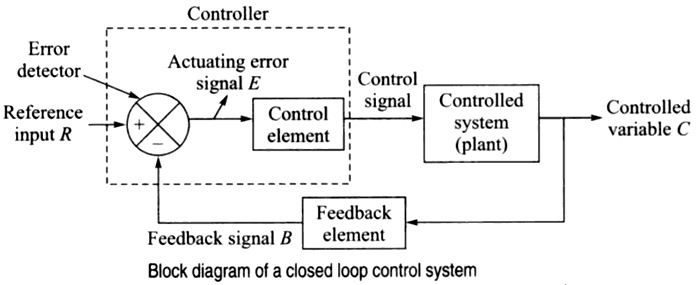
Error detector or comparator: It is a device where the reference input and feedback signal are compared, and if there is a difference, an error signal is generated. Error signal:
Controller: Controller is a device whose input is the error signal and the output is the actuating signal. It acts to reduce the error to zero by making the actual output equal to the desired output. The controller essentially is a comparator.
Feedback element:– It is a device that converts the output variable ‘C’ to another suitable feedback variable ‘B’ to compare with the input command signal. This signal is used to compare with the reference input R.
The feedback is a property of the system by which it permits the output to be compared with the reference input to generate the error signal based on which the appropriate controlling action can be decided. The purpose of feedback is to reduce the error between the reference input and the system output.
Ques 70. ______ signal will become zero when the feedback signal and reference signs are equal.
- Input
- Actuating
- Feedback
- Reference
Explanation:
In a closed-loop control system, the actuating error signal which is the difference between the input signal and the feedback signal (which may be the output signal itself or a function of the output signal and its derivatives and/or integrals)
Actuating signal is proportional to the rate of change of error. Hence if the feedback and reference signal are equal the error will become zero, therefore, the actuating signal will also become zero.
