Important MCQ Question Of DC Generator | Objective Type Question Of DC Generator

Ques 11. In D.C generator the cause of brush wear may be

  1. Rough Commutator surface
  2. Imperfect Contacts
  3. Server Sparking
  4. Any of the Above

Ans 4. Any of the above

Explanation:

  • Brush wear can occur due to many reasons such as server sparking, excessive heat, Imperfect contacts etc.
  • Therefore Brushes required periodic maintenance.


Qus 12. When the number of poles and number of armature conductor are fixed in D.C generator then which winding will give Higher EMF?

  1. Lap Winding
  2. Wave Winding
  3. Either Lap or Wave Winding
  4. Depend upon the conductor

Ans 2. Wave winding

Explanation: As we know that 

  • E.M.F equation of d.c generator is

    Emf equation of dc generator
  • Now for Lap wound generator  A = P
    Where is A = Number of parallel path
    And P = Number of poles
  • Therefor in Lap wound D.C generator they canceled each other.
  • For Wave wound Generator A = 2
  • Therefore the E.M.F is greater in Wave wound D.C generator than Lap wound.


Qus 13. If B is the Flux density, l is the length and v be the velocity of the conductor, then induced EMF is given by

  1. Blv
  2. Blv2
  3. Bl2v
  4. B2lv

Ans 1. Blv

Explanation:

E.M.F induced in the moving conductor
Straight Conductor
  • The area swept by conductor in 1 second = lv
  • The flux cut by conductor in 1 second = Blv
  • Then the emf induced in a straight conductor of length l moving with velocity v perpendicular to a magnetic field B is
    E = Blv
  • Where B,l, and v are mutually perpendicular to each other.


Ques 14. In case of 4 poles D.C Generator Provided with a two layer of Lap winding with sixteen coils, the pole pitch will be

  1. 32
  2. 16
  3. 8
  4. 4

Ans. III. 8

Explanation:

  • Since the winding is two layer winding therefore, the total number of conductor  16 × 2 = 32.
  • Pole pitch of a DC generator is the ratio of the total number of the conductor to the number of poles.
  • Pole pitch = Number of conductor / Number of poles = 32 / 4 = 8
  • Therefore number of pole pitch = 8.


Ques 15. In D.C generator lamination of core material are generally made up of

  1. Cast iron
  2. Stainless steel
  3. Carbon
  4. Silicon Steel

Ans 4. Silicon Steel

Explanation:

  • Eddy current losses can be reduced by using laminated core.
  • But Hysteresis losses can not be reduced in this way.
  • For reducing hysteresis loss those metal are chosen for armature core which has low hysteresis coefficient.
  • Therefore silicon steel such as stalloys is used for armature core.
  • This stalloys not only have low hysteresis coefficient but also possess high electric resistivity.


Ques 16. The thickness of lamination in D.C machine is approx

  1. 5 mm
  2. 0.5 mm
  3. 0.005 mm
  4. 5 mm

Ans 0.5mm

Explanation:

  • According to Faraday’s law of electromagnetic induction rotating armature cuts the magnetic field, due to which an emf is induced in it.
  • This emf generate the eddy current which causes eddy current loss.
  • Therefore to reduce the effect of eddy current the armature core is laminated.
  • The thickness of lamination is between 0.1 to 0.5 mm. 


Ques 17. The resistance of armature winding depends upon

  1. Length of conductor
  2. Cross sectional area of conductor
  3. Number of conductors
  4. Any of the above

Ans 4. Any of the above

Explanation:

  • There are four factors that influence the resistance in a conductor.
    ⇒Thickness (cross sectional area of the wire). (R ∝ 1/A)
    ⇒Length ( R ∝ L)
    ⇒Temperature
    ⇒Conductivity of material
  • The number of armature conductor “Z” is constant that depends upon the number of turns on the armature and the type of winding. i.e wave winding or lap winding.


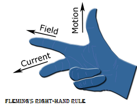
Ques 18. According to Fleming’s Right – Hand Rule for finding the direction of induced emf, When middle finger point in the direction of induced emf forefinger will point in the direction of

  1. Lines of Force
  2. Motion of Conductor
  3. Magnetic Flux Direction
  4. None of the Above

Ans 1. Line of force

Explanation:

  • Fleming’s right-hand rule (for generators) shows the direction of induced current when a conductor attached to a circuit moves in a magnetic field.
  • It can be used to determine the direction of current in a generator’s windings.
    Flemings right hand rule
  • The right hand is held with the thumb, first finger and second finger mutually perpendicular to each other (at right angles), as shown in the diagram.
  • The thumb is pointed in the direction of the motion of the conductor relative to the magnetic field.
  • The forefinger finger is pointed in the direction of the magnetic field. (north to south)
  • Then the middle finger represents the direction of the induced or generated current.


Ques 19. In a commutator

  1. Copper is harder than mica
  2. Mica is harder than copper
  3. Both are equally hard
  4. None of the above

Ans 2. Mica is harder than copper

Explanation:

  • Mica is used as the insulating material for the commutator segments.
  • Due to its mechanical strength and insulating properties, mica is a very satisfactory material.
  • Mica is a good electrical insulator (bad conductor of electricity) at the same time as being a good thermal conductor.
  • Mica is much harder than copper.
  • In Mohs scale for finding hardness from scale 1 to 10 where 1 is the hardest metal.
  • Mica hardness is 2.5.
  • Whereas hardness of copper is 3.


Ques 20. While applying Fleming’s Right – Hand Rule for finding the direction of induced emf, then thumb point towards

  1. Direction of motion of conductor if forefinger points in the direction of generated e.m.f
  2. Direction of induced e.m.f
  3. Direction of flux
  4. The direction of motion of conductor if forefinger point along the line of flux.

Ans 4. The direction of motion of conductor if forefinger point along the line of flux. 

Explanation:

  • The thumb is pointed in the direction of the motion of the conductor relative to the magnetic field.
  • For more information check Que no:18. 

FOR TRANSMISSION AND DISTRIBUTION SYSTEM MCQ CLICK HERE

FOR DC MOTOR MCQ CLICK HERE

FOR 1-Φ INDUCTION MOTOR MCQ CLICK HERE

FOR 3-Φ INDUCTION MOTOR MCQ CLICK HERE

FOR SYNCHRONOUS GENERATOR OR ALTERNATOR MCQ CLICK HERE

FOR SYNCHRONOUS MOTOR MCQ CLICK HERE

FOR DC MOTOR MCQ CLICK HERE

FOR DC GENERATOR MCQ CLICK HERE

FOR POWER SYSTEM MCQ CLICK HERE

FOR TRANSFORMER MCQ CLICK HERE

FOR BASIC ELECTRICAL MCQ CLICK HERE

FOR CONTROL SYSTEM MCQ CLICK HERE

Scroll to Top