Fleming’s Right-Hand Rule
- Fleming’s right-hand rule (for generators) shows the direction of induced current when a conductor attached to a circuit moves in a magnetic field.
- It can be used to determine the direction of current in a generator’s windings.
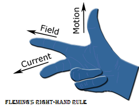
- The right hand is held with the thumb, first finger and second finger mutually perpendicular to each other (at right angles).
- The thumb is pointed in the direction of the motion of the conductor relative to the magnetic field.
- The forefinger is pointed in the direction of the magnetic field. (north to south)
- Then the middle finger represents the direction of the induced or generated current within the conductor (from the terminal with the lower electric potential to the terminal with higher electric potential, as in a voltage source).
Single loop D.C generator
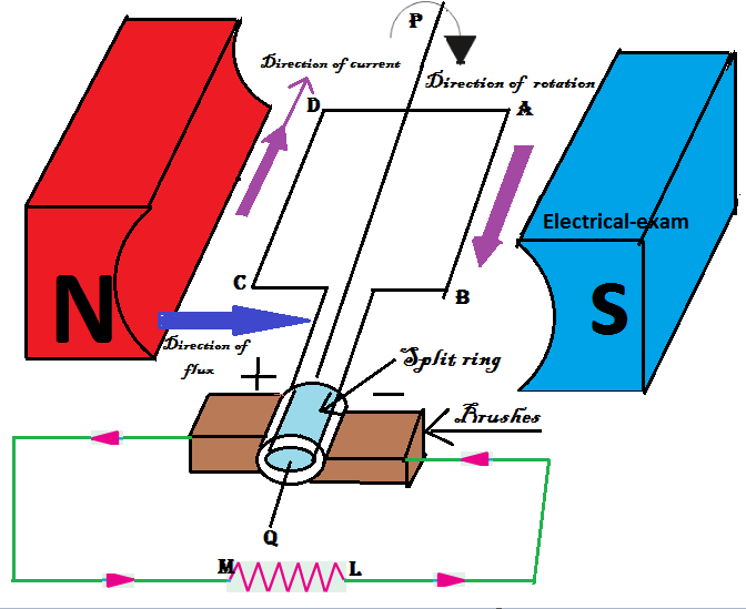
- Let us consider a single loop of conductor ABCD which is placed between to opposite magnetic poles.
- The current will start to circulate in the closed loop.
- The direction of current in D.C generator can be determined by Fleming’s right-hand rule.
- Now by applying Fleming’s right-hand rule, the current will flow from the horizontal position of the coil i.e the current will flow from point C to D and point A to B in another side of the coil.
- Now at this position, the coil is perpendicular to field i.e flux line hence EMF is maximum at this point.
- When the coil is further rotated in its axis and comes in the parallel position to field.
- The upper side of coil will be CD and lower side of coil is AB then the field line can’t pass the coil
- Hence at this position, the EMF is minimum i.e zero so there is no current in the loop.
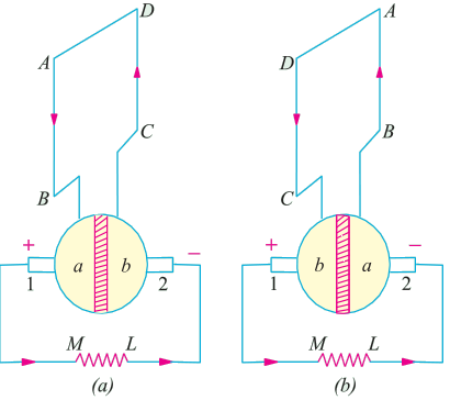
First half of revolution:
- In figure (a) during the first half of revolution the current flow from ABMLCD.
- The segment of a split ring “a” is in contact with brushes “1” which act as the positive end of the supply.
- The segment of split ring “b” is in contact with brushes “2” which act as the negative end of the supply.
Second half of revolution:
- Now in figure (b) during the second half of the revolution the current flow from DCMLBA.
- It is clear that the not only the direction of induced current in the coil is changed but the position of Split ring segment also changes.
- The segment of split ring “b” is in contact with brushes “1” which act as the positive end of the supply.
- The segment of a split ring “a“ is in contact with brushes “2” which act as the negative end of the supply.
- Hence the current from load current still flow from M to L.
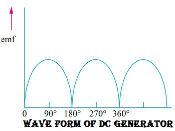
- The current is not in continuous sine waveform although it is unidirectional.
Pages: 1 2