Principle of DC Generator
A D.C generator is a machine which converts mechanical energy into electrical Energy. A D.C generator produces D.C power or current. D.C generator is based on the principle of Faraday’s Law of Electromagnetic Induction.
Faraday’s Law of Electromagnetic Induction
- Faraday’s law of electromagnetic induction describes the relationship between magnetic field and an electric circuit.
- According to the Faraday’s law whenever a conductor is placed in the varying magnetic an E.M.F is induced in the conductor.
- This induced E.M.F causes a current to flow in a closed path since in D.C generator is provided with a closed path.
- The direction of induced E.M.F can be determined by Fleming’s right-hand rule.
From the above discussion, we can say that the essential condition of D.C generator are:-
- Magnetic field
- Conductors which can move as to cut the flux.
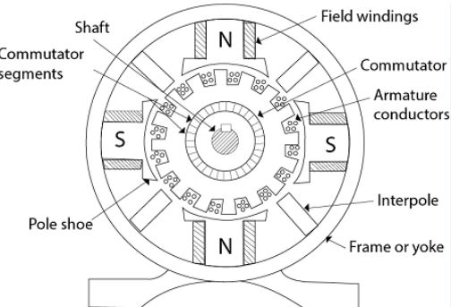
Before going further let us talk about some terms used in DC machine it will help you to understand the topic easily.
Difference between slip ring and split ring
Slip Ring
- The slip ring is a continuous ring which is designed to make continuous contact between the fixed brush contacts.
- The ring contacts on the shaft of a rotation object, provide continuous power to items on the rotating shaft.
- It is used in case of AC supply, where AC is required.
- With slip ring, the voltage in the external circuit varies like a sine wave and the current alternates the direction.
Split ring
- Split ring is also called as commutator
- A commutator has a ring with at least two breaks in it or can be divided into the number of segments.
- The segments are insulated from each other by the thin sheet of Mica or any other insulating material.
- An opposing pair of resulting contacts is wired to opposite poles of the motor.
- A commutator not only allows current to flow but also allows for current reversal (synchronized with the rotation).
- A split-ring commutator makes the current change direction every half-rotation.
- The commutator is responsible for getting DC output although the internal voltage is AC.
So in short, slip rings are for continuous conduction and commutators are for synchronous reversals of the wiring.
When does Minimum and Maximum EMF is induced in the DC Generator?
This can be explained by Faraday’s Law of electromagnetic induction i.e when a magnetic field is cut by moving conductor emf induced in it.
EMF is proportional to the rate of change of magnetic field lines that go through the coil.
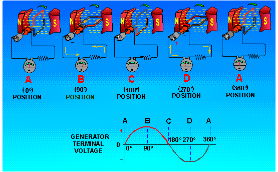
Now from the above figure we can say that
- When the plane of the coil is perpendicular it has lots of magnetic field lines passing through it.
- The maximum EMF will be induced when the coil is perpendicular to the field.
- When the plane of the coil parallel to the field and you have no field lines through the coil.
- EMF is Zero when the coil is parallel to the field.
This can be explained by mathematical expression.
We know that
E = B x l x v
or
E =Blvsinθ
Where
E is the generated voltage
B is the magnetic flux density
l is the length of a conductor in the magnetic field
v is the velocity of the conductor perpendicular to the magnetic lines.
The value of sinθ is maximum at 90 degrees i.e When the coil is perpendicular to the field axis.
The value of sinθ is minimum at 0 degrees i.e when the coil is parallel to the field axis.