Ques 51. When the speed of the DC motor is Increases its Armature current
Increases
Decreases
Remain Constant
Any of the above
Answer 2:-Decreases
Explanation:-
D.C. machines are generally much more adaptable to adjustable speed service. The ready availability of D.C. motors to adjustment of their operating speed over wide ranges and by a variety of methods is one of the important reasons for the strong competitive position of D. C. machinery in modern industrial applications.
Voltage Equation of DC Motor
The voltage equation of the DC Motor is given as
V = Eb + IaRa
The voltage V applied across the motor armature has to (i) overcome the back e.m.f. Eb and (ii) supply the armature ohmic drop IaRa
The above equation can also be written as
Eb = V − IaRa
Back EMF of DC Motor
When the armature of a d.c. the motor rotates under the influence of the driving torque, the armature conductors move through the magnetic field and hence e.m.f. is induced in them as in a generator. The induced e.m.f. acts in opposite direction to the applied voltage V (Lenz’s law) and is known as back or counter e.m.f. Eb.
N – Speed of armature in revolution per minute (r.p.m).
A – Number of parallel paths in the armature winding.
From the above equation, it is clear that the EMF of DC Motor is Directly proportional to the Number of poles of the machine (P), Flux per pole in Weber (ϕ), Total number of armature conductors(Z), and Speed of armature (N)
From the voltage equation and Back EMF equation, we can conclude that
$\begin{array}{l}\dfrac{{P\Phi ZN}}{{60A}} = V – {\rm{ }}{I_a}{R_a}\\\\N = \dfrac{{V – {\rm{ }}{I_a}{R_a}}}{\Phi } \times \left( {\dfrac{{60A}}{{PZ}}} \right)r.p.m\\\\{E_b} = V – {\rm{ }}{I_a}{R_a}\\\\\therefore N = K\dfrac{{{E_b}}}{\Phi }\end{array}$
From the above equation it is clear that by increasing the speed of DC motor the back EMF increased but the armature current decrease.
Ques 52. The amount of back e.m.f. of a shunt motor will increase when
When the Load is Increased
When the Field is Weakened
When the Field is strengthed
None of the above
Answer. 2.When the field is Weakend
Explanation:-
The speed of DC shunt can be controlled by various Methods such as
Flux Control Method
Armature voltage control method
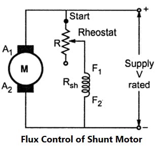
Flux Control Method
The speed of DC Shunt Motor is inversely proportional to the flux. The flux is dependent on the current through the shunt field winding. Thus flux can be controlled by adding a rheostat (variable resistance) in series with the shunt field winding. At Starting the rheostat R is kept at the minimum. The supply voltage is at its rated value. So the current through shunt field winding is also at its rated value. Hence the speed is also rated speed i.e at normal speed. When the resistance R is increased due to which shunt field current Ish decreases, hence decreasing the flux produced. As N =(I/Φ), the speed of the motor increases beyond its rated value. Now as we know that the speed of DC motor is directly proportional to the flux hence when the speed is increased the back EMF also increased. Thus by this method, the speed control above rated value is possible.
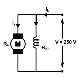
Ques 53. A 250 V, DC shunt motor takes a line current of 20 A. The resistance of shunt field winding is 200Ω and the resistance of the armature is 0.3 Ω Find the armature current and the back e.m.f.
18.75 A, 245 V
25.32 A, 225 V
15.65 A, 100 V
10 A, 150 V
Answer 1.18.75 A, 245 V
Explanation:-
Given Data:-
Supply Voltage V = 250 V Line Current IL = 20A Shunt Resistance Rsh= 200Ω Armature Resistance Ra = 0.3 Ω Armature Current Ia =? Back EMF Eb =?
The Diagram of the given question is shown in figure
(i) Armature current
The Line current of DC shunt motor is the sum of Armature current and Shunt field current
IL = Ia + Ish
And Shunt Field Resistance is given as
Ish = V/Rsh = 250/200 = 1.25 A
∴ Ia = IL − Ish
Ia = 20 − 1.25 = 18.75 A
(ii) Back EMF
The Back EMF of DC Motor is given by
Eb = V − IaRa
= 250 − 18.75 × 0.3 = 250 − 5.625
= 244.375 V ≅ 245 V
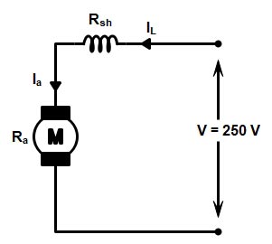
Ques 54. A 4 pole, 250 V, DC series motor has a wave-connected armature with 200 conductors. The flux per pole is 25 mWb when the motor is drawing 60 A from the supply. The armature resistance is 0.15 Ω while the series field winding resistance is 0.2 Ω. Calculate the speed under this condition.
1500 RPM
1470 RPM
1300 RPM
1374 RPM
Answer.4 1374 RPM
Explanation:
Given Data
Supply Voltage V = 250 V
Number of Poles P = 4
Total number of armature conductors Z = 200
Number of parallel paths in the armature winding A = 2 (for wave winding number of parallel path is always 2)
Line current IL = 60 A
Armature current Ia = 60 A ( In DC series motor the line current is equal to the armature current i.e IL = Ia)
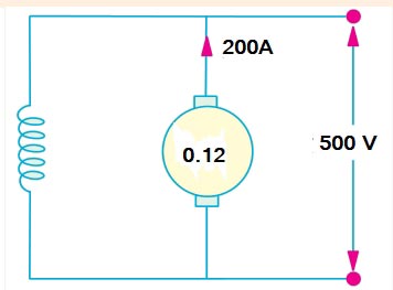
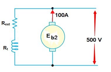
Ques 55. A 500 V shunt motor runs at its normal speed of 250 RPM when the armature current is 200 A. The resistance of armature is 0.12 Ω. Calculate the speed when resistance is inserted in the field reducing the shunt field to 80% of normal value and the armature current is 100A.
420 RPM
540 RPM
320 RPM
1500 RPM
Answer C.320 RPM
Explanation:-
Given that
Supply voltage Vs = 500 V Speed N1 = 250 RPM Armature current Ia1= 200 A Armature Resistance R1 = 0.12Ω
Back EMF of DC Motor is given as
Eb = V − IaRa
Eb = 500 − 200 × 0.12 = 478V
Now when the resistance is inserted in the field, Flux reduce to 80%
Flux Φ2 = 0.8Φ1
Armature current Ia2 = 100A
Back EMF
Eb = V − IaRa
Eb = 500 − 100 × 0.12 = 488V
As we Know that In DC motor the back EMF is directly proportional to the speed and flux.
The voltage V applied across the motor armature has to (i) overcome the back e.m.f. Eb and (ii) supply the armature ohmic drop IaRa
The above equation can also be written as
Eb = V − IaRa
Back EMF of DC Motor
When the armature of a d.c. the motor rotates under the influence of the driving torque, the armature conductors move through the magnetic field and hence e.m.f. is induced in them as in a generator. The induced e.m.f. acts in opposite direction to the applied voltage V (Lenz’s law) and is known as back or counter e.m.f. Eb.
${E_b} = \dfrac{{P\Phi ZN}}{{60A}}$
Where
P – Number of poles of the machine
ϕ – Flux per pole in Weber.
Z – Total number of armature conductors.
N – Speed of armature in revolution per minute (r.p.m).
A – Number of parallel paths in the armature winding.
From the above equation, it is clear that the EMF of DC Motor is Directly proportional to the Number of poles of the machine (P), Flux per pole in Weber (ϕ), Total number of armature conductors(Z), and Speed of armature (N)
From the voltage equation and Back EMF equation, we can conclude that
$\begin{array}{l}\dfrac{{P\Phi ZN}}{{60A}} = V – {\rm{ }}{I_a}{R_a}\\\\N = \dfrac{{V – {\rm{ }}{I_a}{R_a}}}{\Phi } \times \left( {\dfrac{{60A}}{{PZ}}} \right)r.p.m\\\\{E_b} = V – {\rm{ }}{I_a}{R_a}\\\\\therefore N = K\dfrac{{{E_b}}}{\Phi }\end{array}$
The above equation shows that speed is directly proportional to back e.m.f. E b and inversely to the flux Φ
But as the value of armature resistance Ra and series field resistance Rse is very small, the drop IaRa and Ia (Ra + Rse) is very small compared to applied voltage V. Hence, neglecting these voltage drops the speed equation can be modified as,
$N \propto \dfrac{V}{\Phi }$
Ques 57. The shaft torque (Tsh) in a d.c motor is less than total armature torque (Ta) because of ______ in the motor.
Copper losses
Field Losses
Iron and Friction losses
None of the above
Answer 3.Iron and Friction losses
Explanation:-
The torque is developed in the armature and hence gross torque produced is denoted asTa.
The mechanical power developed in the armature is transmitted to the load through the shaft of the motor. It is impossible to transmit the entire power developed by the armature to the load. This is because while transmitting the power through the shaft, there is a power loss due the friction, windage, and iron loss. The torque required to overcome these losses is called lost torque, denoted as Tf. These losses are also called stray losses. The torque which is available at the shaft for doing the useful work is known as load torque or shaft torque denoted as Tsh.
∴ Ta = Tsh + Tf
The shaft torque magnitude is always less than the armature torque, (Tsh < Ta).
Ques 58. The torque developed by a d.c motor is directly proportional to
Flux per pole × Armature current
Armature resistance × Applied voltage
Armature Resistance × Armature current
Square of armature resistance
Answer 1. Flux per pole × Armature Resistance
Explanation:-
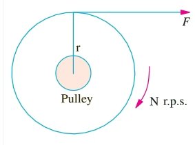
By the term, torque is meant the turning or twisting moment of a force about an axis. It is measured by the product of the force and the radius at which this force acts. Consider a pulley of radius r meter acted upon by a circumferential force of F Newton which causes it to rotate at N r.p.m.
The angular speed of the pulley is
ω = 2πN/60 rad/sec
Work done by this force in one revolution
= Force × distance = F × 2πR Joule
The power developed = Work Done/Time
= (F × 2πR)/60/N
= (F × R) × (2πN)/60
The power developed = T × ω watt or P = T ω Watt
Armature Torque
Let Ta be the torque developed by the armature of a motor running at N r.p.s. If Ta is in N/M, then power developed
P = Ta × 2π N watt
The electrical power converted into mechanical power in the armature = EbIa watt
Power in armature = Armature torque × ω
EbIa = Ta × 2πN/60 or Ta = 9.55EbIa /N (N-m)
The back EMF (Eb) of the motor is given by
EB = PΦZN/60A
Φ = flux per pole in Weber
P = number of poles
Z = total number of armature conductor
N = rotation speed of the armature in revolution per minute (r.p.m)
Hence From the above equation it is clear that the torque of the DC series motor is directly proportional to the armature current (Ia) and Flux per pole(Φ).
T ∝ Ia × Φ
Ques 59. A 4 pole d.c motor takes a 50 A armature current. The armature has lap-connected 480 conductors. The flux per pole is 20 mWb. Calculate the gross torque developed by the armature of the motor.
76.32 N-m
80.34 N-m
50 N-m
25.45 N-m
Answer 1.76.32 N-m
Explanation:-
Given Data
Number of Poles P = 4
The number of parallel Path A = 4 (In Lap wound the number of brushes required by this winding is always equal to the number of poles.)
Ques 60. Armature reaction in a DC motor is increased
When the armature current decreases
When the armature current Increases
When the field current increases
By Interpoles
Answer. 2.When the armature current increases
Explanation:-
When the load is connected to the DC motor, the armature winding of the DC motor carries a current. Every current-carrying conductor produces its own flux so the armature of the DC motor also produces its own flux when carrying a current. So there are two fluxes present in the air gap, one due to armature current while the second is produced by the field winding called main flux. The flux produced by the armature is called armature flux
So the effect of the armature flux on the main flux affects its value and the distribution is called armature reaction.
Armature reaction occurs in DC motors and is caused by the stator magnetic field being distorted, or altered, in reaction to the armature magnetic field. The armature reaction is actually a bending of the motor magnetic field so that the brushes are no longer aligned with the neutral magnetic plane of the motor. If the brushes are not in alignment with this magnetic plane, the current conducted to the armature does not split equally in the armature conductors and therefore causes a voltage difference at the brushes. This causes sparking where the brush meets the commutator. In a motor with a constant load.
We know that reducing the flux leads to an increase in speed, so we can now see that in a machine with a pronounced armature reaction, when the load on the shaft is increased and the armature current increases to produce more torque, the field is simultaneously reduced and the motor speeds up. Though this behavior is not a true case of instability, it is not generally regarded as desirable!
Large motors often carry additional windings fitted into slots in the pole-faces and connected in series with the armature. These ‘compensating’ windings produce an m.m.f. in opposition to the armature m.m.f., thereby reducing or eliminating the armature reaction effect.