Ques 61. In a d.c. motor, the brushes are shifted from the mechanical neutral plane in a direction opposite to the rotation to
Decrease Speed
Increase Speed
Reduce Sparking
Increase torque
Answer 3.Reduce Sparking
Explanation:-
Armature reaction occurs in DC motors and is caused by the stator magnetic field being distorted, or altered, in reaction to the armature magnetic field. The armature reaction is actually a bending of the motor magnetic field so that the brushes are no longer aligned with the neutral magnetic plane of the motor. If the brushes are not in alignment with this magnetic plane, the current conducted to the armature does not split equally in the armature conductors and therefore causes a voltage difference at the brushes. This causes sparking where the brush meets the commutator. In a motor with a constant load.
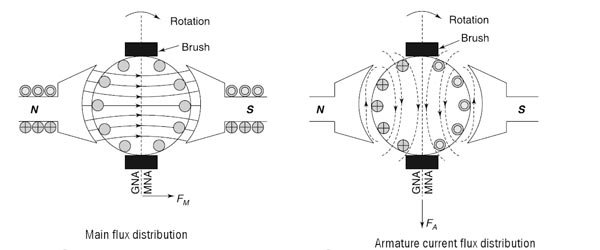
The figure depicts a two-pole generator whose field winding is excited and the direction of the magnetic flux is shown. Note that the flux distribution is uniform. Vector OFM represents the main field. It is observed that the MNA(Magnetic Neutral axis) which is always perpendicular to the field and GNA (Geometrical Neutral Axis) coincide with each other.
The second figure shows an armature connected to a load and armature current flowing through the armature conductors. This armature current produces its own magnetic field. The vector OFA represents the armature field.
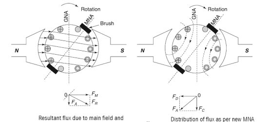
This armature flux interacts with the main flux and a resultant field is produced in the armature as shown in Fig. It can be seen from the figure that the resultant flux is not uniform. It is concentrated at the trailing tips of the pole and is rare (weak) at the leading pole tips. The resultant flux is shown by vector OFR which is the vector sum of OFM and OFA.
Effect of Armature Reaction In DC Machine
Due to armature reaction, mainly two effects are produced which are explained as under.
1. First is the effect of shifting of MNA, which is shown in the above figure
In general, the MNA shifts in the direction of the motion in a generator and in the opposite direction of the motion in a motor. So, in a generator, armature coils undergoing commutation are under the influence of the backward pole. This produces dynamically induced emf in the coils due to the cutting of the flux along the brush axis, which will try to maintain the current in the original direction. In the case of a motor, the coils are under the influence of forward poles. Therefore, there will also be dynamically induced emf in the coils. The extent of MNA shift depends on the value of armature current and hence on the load of the machine.
We know that the commutator must short out the armature coils just at the moment when the voltage across them is zero. When the machine is loaded and the MNA shifts, the brushes short out the coils with some voltage in them. Therefore heavy sparking occurs as the brushes leave a segment. This is a very serious problem as it reduces the brush life and causes pitting of the commutator segments.
Moreover, the MNA shift can also lead to flashover in the commutator bars near the brushes. Air near the brushes in the machine is normally ionized when sparking at the brushes happens. Flashover occurs when the voltage of the adjacent commutator bars is large enough to sustain an arc. If a flashover occurs, the resulting arc can melt the surface of the commutator and cause severe pitting on the commutator surface.
Hence the brushes are shifted from the mechanical neutral plane in a direction opposite to the rotation to reduce sparking.
2. The second major problem caused due to the armature reaction is flux weakening. The vector armature field OFA has two components
(i) OFD which is directly opposite to the main field producing the demagnetizing effect
(ii) OFC which is perpendicular to the main field produces the cross magnetizing effect.
Thus, the armature magnetic field produces:
The demagnetizing effect weakens the main field.
The Cross magnetizing effect distorts the main field.
Flux weakening creates problems in both the machines — generators as well as motors. The voltage supplied by the generator is reduced due to flux weakening for any load. In motors, the effect is even more serious. If the flux in a motor is reduced, the speed of the motor increases. But this increase in motor speed can increase its load, which in turn results in more flux weakening. Due to this flux weakening, a runaway condition may crop up.
Ques 62. Interpoles in a DC motor must be
Series excited and should have the same polarity as that of the behind main pole in the direction of rotation of the armature.
Series excited and should have the same polarity as that of the ahead main pole in the direction of rotation of the armature.
Shunt excited and should have the same polarity as that of the behind main pole in the direction of rotation of the armature.
Shunt excited and should have the same polarity as that of the ahead main pole in the direction of rotation of the armature
Answer 1.Series excited and should have the same polarity as that of the behind main pole in the direction of rotation of the armature.
Explanation:-
Interpoles In DC Machine
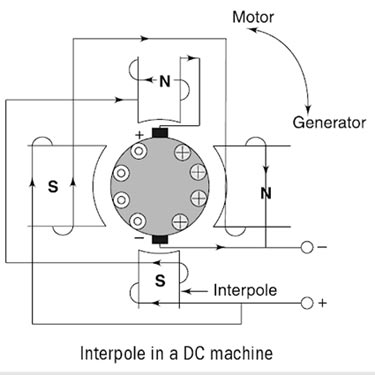
In DC machine One way to reduce the effects of armature reaction is to place small auxiliary poles called “interpoles” between the main field poles. The interpoles have a few turns of large wire and are connected in series with the armature.
One of the disadvantages of armature reaction is brush shifting, therefore a person is always required to adjust the brush position in the machine at every load change. We observe that sparking in the brushes can be avoided if the voltage in the coils undergoing commutation is made zero.
This method tries to do just the same. Small poles called commutating poles or interpoles are introduced in between the main poles along the geometrical neutral axis. Brushes are also set on this axis and kept fixed at this position for all the loads. The interpole winding has fewer turns of heavy copper conductors.
Interpoles are connected in series with the armature winding so that they carry full armature current, as shown in Fig. As the load on the machine is increased, the current passing through the interpoles also increases, hence the flux produced by the interpoles is very large. Consequently, the large voltage is induced in the conductor that opposes the voltage due to the neutral plane shift and the net result is that they neutralize each other.
Note that the interpoles can be used equally effectively in motors as well as in generators. When the mode of operation of the machine changes from the motor to the generator, the currents in the armature and the interpoles is reverse in direction. Therefore, their voltage effects cancel each other out.
Thus, we can conclude that:
In a generator, interpoles must have the same polarity as the next upcoming pole.
In a motor, interpoles must have the same polarity as the previous main pole.
The mmf induced on the interpoles must be sufficient enough to neutralize the effect of armature reaction and to produce enough field in the interpole winding to overcome the reactance voltage due to commutation.
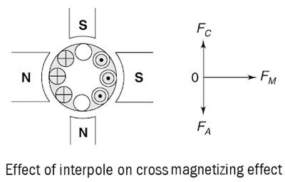
Another important function of the interpole is to neutralize the cross-magnetizing effect of the armature reaction, as shown in Fig. Here, vector FM represents the mmf due to main poles, FA represents the cross-magnetizing mmf due to the armature reaction and FC represents the interpole mmf which is directly opposite to the FA so that they cancel each other out.
It is important to note here that the interpoles do not affect the flux distribution under the pole faces. So, even by using the interpoles in the machine, the flux weakening problem is not completely eliminated. Most medium-sized general-purpose motors correct the sparking problems with the interpoles and just live with the flux weakening problems.
Main Functions of the Interpole
The Interpole neutralizes the reactance voltage and gives a spark-free commutation.
It neutralizes the cross-magnetizing effect of armature reaction so that the brushes are not required to be shifted from their original position for any load.
Ques 63. In very large d.c. motors with severe heavy-duty, armature reaction effects are corrected by
Using interpoles Only
Using compensating winding in addition to interpoles
Shifting the brush position
None of the above
Answer 2.Using compensating winding in addition to interpoles
Explanation:-
As is clear from the above discussion,(ques 62) use of interpoles does eliminate the effect of cross-magnetizing effect but it still does not remove the effect of the flux weakening problem of the DC machine.
Moreover, interpoles are effective only in the commutating zone, which means that the armature reaction effect is removed only under the interpoles while another periphery of the armature is not affected. This is a very serious problem in large machines.
Some large d.c. motors employed in steel mills perform a series of heavy-duty operations. They accelerate, decelerate, stop, reverse all in a matter of seconds. The corresponding armature current increases, decreases, reverses in the stepwise fashion, producing very sudden changes in armature reaction. For such motors, interpoles do not adequately neutralize the armature m.m.f.
To eliminate this problem, additional compensating windings are connected in series with the armature.
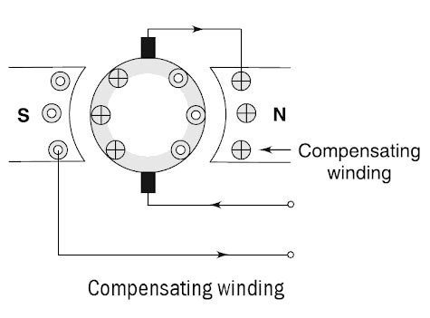
In this method, a winding called, compensating winding, is placed in the carved-in faces of the main poles to cancel the effect of the armature reaction and to maintain uniform flux distribution under the main poles.
Compensating winding is connected in series with the armature winding in such a way that the current flowing in them is directly opposite to the current flowing in the armature located just below the pole faces. Half of the conductors (say the left-hand side of the pole) is connected in series with the other half of the conductors (on the right side of the adjacent pole). The compensating winding is shown in Fig.
The MMF produced by the compensating winding is equal and opposite to the MMF produced by the armature at every point under the pole faces. Hence the net MMF is just equal to the MMF produced by the main poles alone. As a result, the flux in the machine remains unchanged regardless of the load on the machine.
Ques 64. A 440-V shunt motor has armature resistance of 0.8 Ω and field resistant 200 Ω. What will be the back e.m.f when giving an output of 7.46 kW at 85 percent efficiency.
567.2 V
345.4 V
425.8 V
645 .34 V
Answer. 3.425.8V
Explanation:-
Given data
Supply Voltage V = 440 V Armature Resistance Ra = 0.8Ω Field Resistance Rsh = 200Ω Motor Output ηout = 7.46 kW = 7460 Watt Motor Efficiency η = 85% = 0.85
The efficiency of the motor is given as
η = Motor Output power ⁄ Motor Input power
Motor Input Power = Motor Output Power ⁄ Efficiency
= 7460 ⁄ 0.85 = 8776.4 Watt
Now the Motor Line current or the Input current IL = P ⁄ V
IL = 8776.4 ⁄ 440 = 19.95 A
The Line current of DC shunt motor is the sum of Armature current and Shunt field current
IL = Ia + Ish
And Shunt Field Resistance is given as
Ish = V/Rsh = 440/200 = 2.2 A
∴ Ia = IL − Ish
Ia = 19.95 − 2.2 = 17.75 A
The Back EMF of DC Motor is given by
Eb = V − IaRa
= 440 − 17.75 × 0.8 = 440 − 14.2
= 425.8 V
Ques 65. A 4 pole, lap wound d.c motor has 540 conductors and 230 V supply. The armature resistance is 0.8Ω. Its speed found to be 1000 r.p.m. the flux per pole is 25 mWb. The Induced e.m.f.and Armature current will be
250 V, 10 A
300 V, 6.25 A
225 V, 10 A
225 V, 6.25 A
Answer. D.225 V, 6.25A
Explanation:-
Given Data
Number of Poles P = 4
The number of parallel Path A = 4 (In Lap wound the number of brush required by this winding is always equal to the number of poles.)
Total number of armature conductor Z = 540
Flux per Pole Φ = 20 mWb = 25 x 10-3 Wb,
Armature current Ia=?
Back EMF Eb =?
(i) Back EMF of DC motor
${E_b} = \dfrac{{P\Phi ZN}}{{60A}}$
= (PΦZN)/(60A) = (25 x 10 -3 x 4 x 1000 x 540)/(60 x 4) = 225 V
Eb = 225 V
(ii) Armature current
From the voltage equation the back EMF of DC motor is
Eb = V − IaRa 225 = 230 − 0.8Ia
Ia = 6.25 A
Hence the back EMF is 225 V and Armature current is 6.25 A
Ques 66. A short shunt compound generator supplies a load current of 100 A at 250 V. The generator has the following winding resistances:
shunt field = 130Ω, Armature 0.1 Ω and series field = 0.1 Ω . Find the Emf generated if the brush drop is 1 V per brush.
272.2 V
262.2 V
272.0 V
262.0 V
Answer.1. 272.2 V
Explanation:-
Voltage = 250 V
Load current (IL) = 100 A
Shunt field (Rf) = 130Ω
Armature field (Ra) = 0.1Ω
Series field (Rse) = 0.1Ω
Brush voltage Drop = 1V
Now voltage drop in the field winding = ILRse
= 100 x 0.1 = 10 V
For short shunt compound generator, the voltage drop across series field winding gets added with voltage drop across armature winding
Voltage drop across field winding + Voltage drop across armature winding
V1 = 250 + 10 = 260 V
Field current If = V1/Rf = 260/130 = 2 A
So armature current
Ia = IL + If = 100 + 2 = 102 A
Generated EMF
E = V1 + IaRa
= 260 + 102×0.1
E = 270.2 Volt
Ques 67. In flux control method the speed of DC motor is obtained _____
Above Base speed
Below base speed
Both above and below base speed
Remain constant
Answer 1. Above base speed
Explanation:-
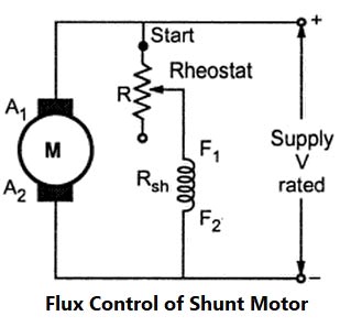
Flux Control Method
The speed of DC Shunt Motor is inversely proportional to the flux. The flux is dependent on the current through the shunt field winding. Thus flux can be controlled by adding a rheostat (variable resistance) in series with the shunt field winding. At Starting the rheostat R is kept at the minimum. The supply voltage is at its rated value. So the current through shunt field winding is also at its rated value. Hence the speed is also rated speed i.e at normal speed. When the resistance R is increased due to which shunt field current Ish decreases, hence decreasing the flux produced. As N =(I/Φ), the speed of the motor increases beyond its rated value. Now as we know that the speed of DC motor is directly proportional to the flux hence when the speed is increased the back EMF also increased. Thus by this method, the speed control above rated value is possible.
Ques 68. The method of speed control of DC Shunt motor is used for applications where a very wide range sensitive speed control is required is
Ward-Leonard system
Multiple Voltage Control
Tapped field control
Rheostatic Control
Answer.1. Ward-Leonard system
Explanation:-
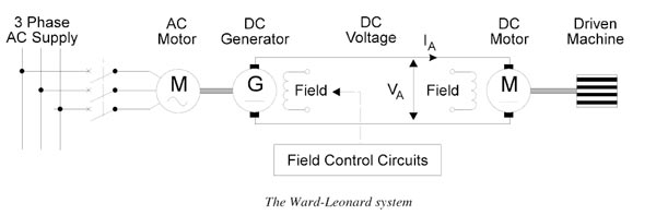
Ward-Leonard system.
The Ward-Leonard system comprises a fixed speed 3-phase AC induction motor driving; separately excited DC generator that, in turn, feeds a variable voltage to a shunt wound DC motor. So this is essentially a DC variable speed drive.
The basic principle of the DC variable speed drive is that the speed of a separately excited DC motor is directly proportional to the voltage applied to the armature of the DC motor. The main changes over the years have been concerned with the different methods of generating the variable DC voltage from the 3-phase AC supply.
In the case of the Ward-Leonard system, the output voltage of the DC generator, which is adjusted by controlling the field voltage, is used to control the speed of the DC motor. This type of variable speed drive had good speed and torque characteristics and could achieve a speed range of 25:1. It is no longer commonly used because of the high cost of the 3 separate rotating machines. In addition, the system requires considerable maintenance to keep the brushes and commutators of the two DC machines in good condition.
Advantages of Ward-Leonard system.
Wide range of sensitivity can be obtained by using this method.
The absence of an external resistance improves the efficiency at all speeds.
No special starting gear is required
As the generator induced voltage is gradually raised from zero, the motor starts up smoothly
Speed reversal is smoothly carried out.
Disadvantages of Ward-Leonard system.
The initial cost of the system is high as there is a motor-generator set installed, of the same rating as that of the main DC motor.
Larger size and weight.
Requires large floor area
Costly foundation
Maintenance of the system is frequent.
The overall efficiency of the system is not sufficient, especially it is lightly loaded.
Application of Ward-Leonard System
Colliery Winders
Cranes
Electric Excavators
Mine hoists
Elevators
Steel rolling mills
Paper Machines
Ques 69. Two DC series motors connected in series draw current I from supply and run at speed N. When the same two motors are connected in parallel taking current I from the supply, the speed of each motor will be
N/2
N
2N
4N
Answer D. 4N
Explanation:-
In case of series.
When motor are connected in series and are in running position, Speed ∝ (voltage) ∝(V/2) (i) (Since the voltage across each motor = V/2 ) and current is Ia.
Ns ∝ V/2I
In case of parallel
When the motor is connected in parallel and are in running position, Speed ∝ (voltage) (V). (Since the voltage across each motor = V ) and current is Ia/2
Np ∝ 2V/I
From both the equation
Ns/Np = V/2I/2V/I
N parallel = 4Nsereis
or
Hence it can be concluded that for the for low-speed operation motor may be connected in series and for high-speed operation motor is connected in parallel.
Ques 70. A dc series motor has an armature resistance of 0.06 Ω and series field resistance of 0.08 Ω. The motor is connected to a 400 V supply. The line current is 20 A when the speed of the machine is 1100 rpm. When the line current is 50 A and the excitation is increased to 30%, the speed of the machine in rpm is