1. How many generators are used in the Delayed time base oscillators?
4
2
6
1
Answer.2. 2
Explanation:
A delayed time base oscilloscope has two base generators, a normal time base, and an additional delayed time base, which is superimposed on the normal time base output.
This facility allows any portion of a displayed waveform to be brightened when the oscilloscope is operating on a normal time base.
2. In delay time base oscilloscope switching to delayed time base causes
Decrease screen brightness
Increase screen Brightness
Completely fill the screen
Partially fill the screen
Answer.3. Completely fill the screen
Explanation:
In delay time base oscilloscope switching to delayed time base causes the brightened portion to completely fill the screen for detailed investigation.
3. In delay time base oscilloscope, the input signal of the vertical plates is delayed for
Infinite Time
Finite-time
10 Sec
1 Minute
Answer.2. Finite-time
Explanation:
In delay time base oscilloscope the input signal of the vertical plates is delayed by some finite time with delay circuit. The signal before the delay circuit is applied to the trigger time base circuit to the horizontal section. This allows the study of all leading or lagging edges of a pulse-type waveform.
4. The additional time base generator in the delay time base oscilloscope is superimposed on
Normal Time base Generator
Normal Time base Generator Output
Voltage Comparator
Additional time base Generator output
Answer.4. Additional time base Generator output
Explanation:
The delayed time base oscilloscope uses two-time base generators. One is a normal time base while the other one is an additional time base generator. The additional time base generator is superimposed on the additional time base generator output. Due to this additional time base, the waveform can be brightened when the oscilloscope is running on a normal time base.
5. In Delay time base oscilloscope ______ base circuit is used for main time base circuits.
Normal time base
Delay time base
Summing circuit
Deflection circuit
Answer.4. Additional time base Generator output
Explanation:
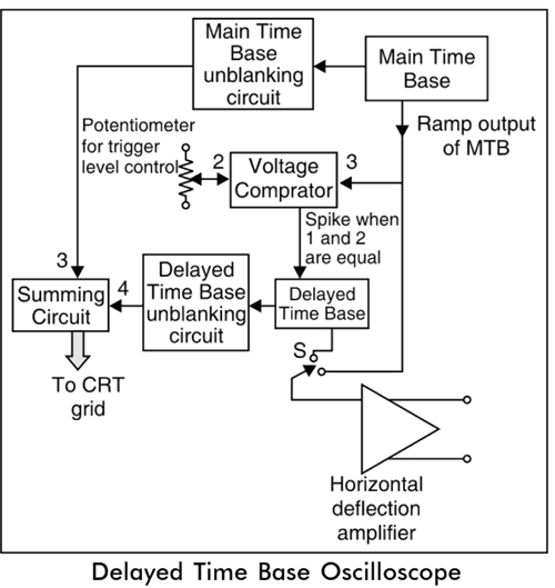
In Delay time base oscilloscope the normal time base circuit is used for main time base circuits which works the same as in other oscilloscopes.
The main time base unblanking circuit produces an unblanking pulse which is applied to CRT grid to turn on an electron beam in the CRT during the sweep time.
The ramp output of the main time base is applied to the vertical comparator and to the horizontal deflection amplifier through the switch.
The other input to the voltage comparator is derived from the potentiometer whose level is adjustable.
6. The ramp output of the main time base is applied to the _______ in the Delayed time base oscilloscope.
Main time base Unblanking circuit
Voltage Comparator
Horizontal amplifier
Both 2 and 3
Answer.4. Both 2 and 3
Explanation:
In Delay time base oscilloscope the normal time base circuit is used for main time base circuits which works the same as in other oscilloscopes.
The main time base unblanking circuit produces an unblanking pulse which is applied to CRT grid to turn on an electron beam in the CRT during the sweep time.
The ramp output of the main time base is applied to the vertical comparator and to the horizontal deflection amplifier through the switch.
The other input to the voltage comparator is derived from the potentiometer whose level is adjustable.
When the levels of ramp output of the main time base and trigger level set by potentiometer are equal then the voltage comparator produces a negative or positive output spike at that instant.
This spike triggers the delayed time base circuit.
The main time base and delayed time base unblanking circuit produces an unblanking pulse during the ramp time of the delayed time base. The unblanking pulse from these is applied to the summing circuit and then applied to the CRT.
7. When the levels of ramp output of the main time base and trigger level are equal then the voltage comparator produces ______
Negative spike Only
Positive spike Only
Both negative and Positive spike
None of the above
Answer.3. Both negative and Positive spike
Explanation:
In Delay time base oscilloscope the normal time base circuit is used for main time base circuits which works the same as in other oscilloscopes.
The main time base unblanking circuit produces an unblanking pulse which is applied to CRT grid to turn on an electron beam in the CRT during the sweep time.
The ramp output of the main timebase is applied to the vertical comparator and to the horizontal deflection amplifier through the switch.
The other input to the voltage comparator is derived from the potentiometer whose level is adjustable.
When the levels of ramp output of the main time base and trigger level set by potentiometer are equal then the voltage comparator produces a negative or positive output spike at that instant.
This spike triggers the delayed time base circuit.
The main time base and delayed time base unblanking circuit produces an unblanking pulse during the ramp time of the delayed time base. The unblanking pulse from these is applied to the summing circuit and then applied to the CRT.
8. In Delay time base oscilloscope the delay ensure ________
Lost waveform
No Waveform is lost
High Accuracy
High Brightness
Answer.2. No Waveform is lost
Explanation:
The delay ensures that no part of the waveform gets lost, In a delayed timebase oscilloscope, a variable time delay circuit is used in the basic time base circuit. This allows the triggering of sweep time after the delay time. Thus the delay time is variable. After this, the sweep is triggered for the time (. Then the portion of the waveform for the time gets expanded on the complete oscilloscope for the detailed study.
9. During the Delayed time base period, the voltage applied to the CRT grid is almost ______ the voltage corresponding to the Main time base period.
Twice
Equal
Half
Thrice
Answer.2. No Waveform is lost
Explanation:
The input to the voltage comparator is derived from the potentiometer whose level is adjustable. The unblinking pulses from MTB and DTB are added by the summing circuit and given to the CRT grid. The unblinking pulse of MTB produces a trace of uniform intensity.
But during ramp time of DTB, the addition of two pulses decides the intensity of the trace on the screen. Hence during DTB time, the voltage applied to the CRT grid is almost twice the voltage corresponding to MTB time.
10. The application of delayed time base oscillator is
Used to extend waveform
Rising and falling edges pulse measurement
Both 1 and 2
None of the above
Answer.3. Both 1 and 2
Explanation:
Applications of Delayed Time Base Oscilloscope
It is used to extend any part of the waveform on the entire screen of the oscilloscope and make it bright to analyze the desired portion of the waveform.
The rising and falling edges of the pulses are investigated with a delayed time-based oscilloscope.
If the input is pulse waveform and leading-edge is used to trigger the delay time. then lagging edge can be displayed to fill the entire oscilloscope screen.
Similarly, if the lagging edge is used to trigger the delay time then the leading edge will be displayed on the entire screen.
If the time delay is perfectly adjusted, then any portion of the waveform can be extended to fill the entire screen.