Ques 31. The potential transformers’ Nominal Ratio is defined as the ratio of:
Primary winding voltage and secondary winding voltage
Rated primary winding voltage and rated secondary winding voltage✓
Primary winding turns and secondary winding turns
Any of the above
The nominal ratio of the potential transformer (Kn) is defined as the ratio of rated primary quantity to the rated secondary quantity, either current or voltage.
Ques 32. Whenever a 3–phase fault takes place at the terminals of an induction generator, the sustained fault current is:
Equal to the full load current
About 20 times the full load current
Much less than the full load current✓
About 10 times the full load current
The unsaturated synchronous reactance is used for sustained fault current calculation. When sustained faults occur, nearby generators and motors will be demagnetized and generator impedance will increase.
When generator impedance increases to its synchronous value, generator short-circuits current may be much less than generator full-load current. This may significantly reduce the available fault current.
Voltage restrained overcurrent relays may be needed to detect short-circuit current that approaches generator full-load current.
Ques 33. For complete protection of a 3-phase line
Three-phase and three–earth fault relays are required
Three-phase and two–earth fault relays are required
Two-phase and two–earth fault relays are required
Two-phase and one–earth fault relays are required✓
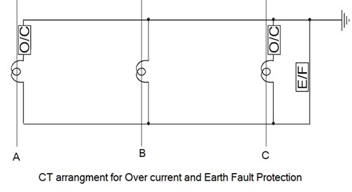
Phase-to-earth faults are covered by earth fault relays. The most common form of earth fault protection operates on the principle that the vector sum of currents flowing in a balanced three-phase system equals zero.
As shown in the figure only two phases need to be monitored by the overcurrent relay, the reason being that a fault on the third phase will be either to one of the other two phases or to earth. A phase-to-earth fault will cause an unbalance in the three phases, resulting in a current flowing in the earth fault element, tripping the earth fault relay.
Earth fault protection is by nature more sensitive than overcurrent protection and will clear a fault a lot quicker. That is the reason, for example, that certain types of the power cable are individually screened, with the metal screen earthed during installation. This ensures that a cable fault will be a single phase-to-earth fault before a three-phase fault develops, in order that the fault can be cleared quickly by the earth fault protection.
Ques 34. When two transformers of different kVA ratings are connected in parallel they share the load in proportion to their respective kVA rating only when their:
KVA ratings are identical
Efficiencies are equal
PU Impedance is equal✓
Equivalent impedance is equal
Same percentage impedance
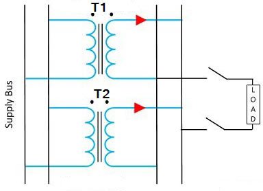
If two transformers are connected in parallel with similar per-unit impedances they will mostly share the load in the ratio of their KVA ratings.
A difference in the ratio of the reactance value to the resistance value of the per-unit impedance results in a different phase angle of the currents carried by the two paralleled transformers; one transformer will be working with a higher power factor and the other with a lower power factor than that of the combined output. Hence, the real power will not be proportionally shared by the transformers.
Ques 35. The most efficient torque producing an actuating structure for induction type relay is:
Shaded pole structure
Watt-hour-Meter structure
Induction – cup Structure✓
Single – Induction Loop Structure
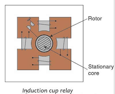
The schematic arrangement of the induction cup structure is shown in Fig. It closely resembles an induction motor except for rotor iron is stationary, only the rotor conductor portion being free to rotate. The moving iron is a hollow metal cylinder or cup, which turns on its axis.
A stationary iron core is placed inside the rotating cup to decrease the air gap without increasing inertia. The spindle of the cup carries an arm that closes contacts. A spring is employed to provide a resetting torque. When two actuating quantities are applied, one may produce an operating torque while the other may produce restraining torque. Brake magnets are not used with induction cup-type relays.
Two pairs of coils produce a rotating field which induces the current in the rotor. Torque is produced due to the interaction between the rotating flux and the induced current, which causes rotation. The inertia of the cup is much less than that of a disc.
The magnetic system is more efficient and hence the magnetic leakage in the magnetic circuit is minimized. This type of magnetic system also reduces the resistance of the induced current path in the rotor. Due to the low weight of the rotor and efficient magnetic system its torque per VA is about three times that of an induction disc type construction.
Thus, its VA burden is greatly reduced. It possesses high sensitivity, high speed and produces a steady non-vibrating torque. Its parasitic torques due to current or voltage alone are small. Its operating time is in the order of 0.01 seconds. Thus with its high torque/inertia ratio, it is quite suitable for higher speeds of operation. This type of structure is more efficient torque produced than either the shaded-pole or the watt-hour structure.
Ques 36. Triac is usually operated at:
All frequencies
High frequencies Only
Power Frequency✓
None of these
The TRIAC is a three-terminal semiconductor device for controlling current. It gains its name from the term TRIode for Alternating Current.
Power frequency:- A frequency in the range used for alternating currents supplying power (commonly 50 or 60 Hz).
Triacs are the bidirectional controllable device. It is more vulnerable to transients and inductive loads. Mostly triacs are used in ac regulators (at a power frequency of 50 or 60 Hz).
Ques 37. Earth wire on EHV overhead transmission line is provided to protect the line against:
Lightning Surge✓
Switching Surge
Excessive fault Voltage
Corona Effect
Earth wire is also called the guard wire and it mainly protects lines from lightning. If in case of lightning strikes then it carries the excessive current inrush to the ground.
Its radius is much smaller than the actual transmission wire because the resistance is inversely proportional to an area of cross-section and as the cross-section decreases, the resistance increases.
The increased resistance of earth wire is able to withstand a high inrush of current caused due to lightning and it will safely guide this inrush into the ground.
It is placed above all the conductors mainly because if lightning strikes then it will strike at the uppermost point in the line configuration and protect the actual conductors.
Ques 38. The measurement range of a milliammeter can be increased by using a:
High resistance in shunt
Low resistance in shunt✓
High resistance in series
Low resistance in series
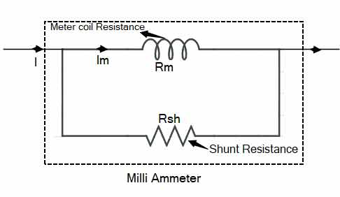
The Range of the DC milliammeter can be extended by using resistance in parallel. The shunts are low resistances used in ammeters for range extension. The shunt is made of Manganin or Constantan depending on whether it is used for DC or AC.
With Im as the current flow through the meter capable of producing the maximum deflection, precautions are to be taken to ensure that the current through the meter coil is limited to Im. However, when the current to be measured is large, the alternative path is provided via, the low resistance shunt Rsh.
Ques 39. Three equal resistors, connected in series across a source of emf, dissipated 10W of power. What would be the power dissipated in the same resistor when they are connected in parallel across the same source?
10 W
30 W
90 W✓
270 W
When the three resistors are in series, effective resistance in the circuit = 3R
Power dissipated in the series circuit = Pseries = V2/(3R) = 10 W
⇒ V2/(R) = 30 W
When the three resistors are in parallel, effective resistance in the circuit = R/3.
Power dissipated in the parallel circuit = Pparallel = V2/(R/3) = 3V2/(R)
= 3 x 30 W = 90 W.
Ques 40. If a 3-phase, 400V, 50Hz, 4 pole induction motor is running at a slip of 5% then the relative speed of the rotor field with respect to the stator field is:
Zero
75 RPM✓
142.5 RPM
1500 RPM
Given Frequency = 50 Hz Number of Poles = 4 pole Slip = 5% = 0.05
Synchronous Speed is given as
Ns = 120f/P
= 120 × 50/4
= 1500 RPM
Speed of Rotor
Nr = (1 – s)Ns
Nr = (1 – 0.05)1500
Nr = 1425 RPM
In the steady-state both the rotor and stator magnetic fields rotate in synchronism, so the speed of the rotor field with respect to the stator field would be zero.
The speed of the rotor which respects to the stator field is (Nr – Ns)