Ques 51. In order to switch off and EHV circuit for maintenance, the following sequence is adopted:
Open the circuit breaker, open the isolator, operate the earth switch✓
Operate the earth switch, open the isolator, open the circuit breaker
Open the isolator, operate the earth switch, open the circuit breaker
Open the isolator, open the circuit breaker, operate the earth switch
Switching sequence – to turn on or off a bus bar, equipment, power plant requires proper steps and skill. A single mistake would cause an accident.
Step 1: Open the circuit breaker: CB is a device that can make and break the circuit under normal as well as under faulty conditions manually or automatically.
Step 2: Open the isolator: An isolator is a device that always operates under no-load conditions. This is because it has no provision for arc quenching.
Its function is to isolate the circuit after operation of the circuit breaker and discharge the grapes charges to earth through the earth switch.
Step 3: Operate the Earth switch: After opening the circuit breaker and manually disconnecting the isolator the next is to engage the earth switch. Its function is to discharge any remnant charge due to residual magnetism which might be lethal to humans and expensive testing equipment.
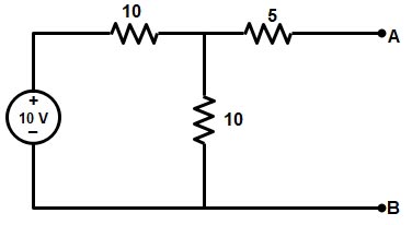
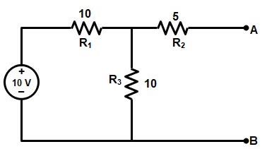
Ques 52. For the circuit given in the fig, the Thevenin’s voltage and resistance as seen at AB are represented by:
5 V, 5 Ω
10V, 10 Ω
5 V, 10 Ω✓
54V, 15 Ω
The Thevenin voltage e used in Thevenin’s Theorem is an ideal voltage source equal to the open circuit voltage at the terminals. In the example below, the resistance R2 does not affect this voltage and the resistances R1 and R3 form a voltage divider, giving
The Thevenin resistance r used in Thevenin’s Theorem is the resistance measured at terminals AB with all voltage sources replaced by short circuits and all current sources replaced by open circuits. It can also be calculated by dividing the open-circuit voltage by the short circuit current at AB, but the previous method is usually preferable and gives
Hence the Thevenin’s Voltage is 5 V and the Thevenin’s Resistance is 10Ω
Ques 53. Why are shunt reactors connected at the receiving end of a long transmission line system?
To increase the terminal voltage
To compensate voltage rise caused by capacitive charging at light load✓
To improve the power factor
None of these
A long transmission line can be considered to be composed of a high amount of capacitance and inductor distributed across the entire length of the line. Ferranti Effect occurs when the current drawn by the distributed capacitance of the line is greater than the current associated with the load at the receiving end of the line which occurs during light or no load.
Shunt Reactor compensation at the receiving end help to reduce the effect of capacitance thus reducing the Ferranti effect.
The shunt Reactor absorbs the excess reactive power during no load or light load conditions and thus helps in stabilizing the voltage of the Transmission Line.
Ques 54. A 10Ω resistor is connected in parallel with a 15Ω resistor and the combination in series with a 12Ω resistor. The equivalent resistance of the circuit is:
37 Ω
27 Ω
18 Ω✓
None of these
Since the resistor 10Ω and 15Ω are connected in parallel, therefore, its equivalent resistance
= (10 × 15) ÷ (10 + 15) = 6Ω
Now 6Ω and 12Ω are connected in series hence total resistance is
= 6 + 12 = 18Ω
Ques 55. A nickel coil has a resistance of 13Ω at 50 °C. If the temperature coefficient of resistance at 0°C is 0.006/°C, the resistance at 0°C is
16.9 Ω
10 Ω✓
43.3 Ω
None of these
When a conductor of resistance Ro at 0°C is heated to t° C. Its resistance Rt after heating is given by
Rt = Ro (1 + tα t)
13 = Ro(1 + 50 × 0.006)
13 = 1.3 Ro
Ro = 13 ÷ 1.3 = 10Ω
Ques 56. The energy used by a 1.5 kW heater in 5 minutes is:
45,000 J✓
450 J
7500 J
None of these
Electric energy is the total amount of electrical work done in an electrical circuit. Electric energy can also be defined as the product of power and time. The S.I Unit of Electrical- Energy is joule or watt-sec.
1.5 kW = 1500 joule
time = 5 minute = 5 × 60 = 300 sec
Electric Energy = 1500 × 300 = 45,000 Joules
Ques 57. What is called the Electro-Motive Force (EMF) of a voltage source?
Terminal voltage when the load is applied
Internal voltage when no load is applied✓
The product of internal resistance and load current
The electric pressure provided to the load
Emf is not a force at all; it is a special type of potential difference. To be precise, the electromotive force (emf) is the potential difference of a source when no current is flowing. Units of emf are volts.
If there is no load connected to the Voltage source, then no-load current will flow, and there will no internal voltage drop.
The voltage appearing across the voltage source’s terminals under this condition is called its open-circuit voltage or no-load voltage which exactly equals the electromotive force (e.m.f. of that source).
A voltage source open-circuit, or no-load, voltage corresponds to its electromotive force.
Ques 58. A permanent magnet moving coil ammeter has a coil resistance of 99 ohm and a Full-Scale Deflection (FSD) current of 0.1mA. Shunt resistance is 1 ohm. Current through the meter at 0.5 F.S.D is:
0.007 mA
0.05 mA✓
0.023 mA
None of these
Full scale deflection 0.1 mA
Now current through 0.5 FSD = 0.5 × 0.1 = 0.05 mA
Ques 59. For power measurement of the three-phase circuit by two wattmeter method, when the value of power factor is less than 0.5 lagging:
One of the wattmeters will read zero
Both give the same readings
One of the wattmeter connections will have to be reversed✓
Pressure coil of the wattmeter will become ineffective
When one wattmeter reads negative during the measurement of power by two wattmeter method. The power factor of the load in such a case will be less than 0.5 lagging.
Wattmeter cannot show negative reading as it has only a positive scale. An indication of negative reading is that the pointer tries to deflect in a negative direction i.e. to the left of zero. In such a case, reading can be converted to positive by interchanging either pressure coil connections or by interchanging current coil connections. Remember that interchanging connections of both the coils will have no effect on wattmeter reading.
Ques 60. One international ohm is equal to
1.00049 absolute ohm✓
0.99951 absolute ohm
0.969 absolute ohm
1.049 absolute ohm
A unit of resistance, equal to that of a column of mercury of uniform cross-section that has a length of 160.3 centimeters and a mass of 14.4521 grams at the temperature of melting ice; it has been superseded by the ohm, and is equal to 1.00049 ohms.