
Ques 11. A synchronous Generator is a source of
- Real Power
- Reactive Power
- Apparent Power
- Both real and Reactive Power✓
Reactive power is required at the user end to establish and sustain magnetic fields. It is through a magnetic field that energy transformation in a usable form takes place. Reactive power is generated at the utility end through their generators, to begin with. It may be noticed that active power flow is always from a utility to a user. Reactive power flow is bi-directional. Synchronous generators are the main sources of active power generation in a power system, however, they are also able to provide reactive power to fulfill transmission requirements. Synchronous generators with the primary function of producing and supplying electric power; Synchronous motors with the primary function of converting electrical power into mechanical power; Synchronous condensers with the primary function of providing only reactive power. Active and reactive power demands vary as conditions in the system change. When loads are heavy, the transmission system absorbs reactive power. In such cases, synchronous generators add reactive power to the grid. When loads are light, thank mission systems can become overloaded. In those cases, the synchronous generator must absorb reactive electricity from the system. Due to these varying generate. An over-excited synchronous generator, that is, greater than nominal excitation, generates reactive power whilst an under-excited machine absorbs it. Synchronous generators are the main source of supply to the power system of both positive and negative VArs.
Ques 12. In an induction motor, if the air gap is increased
- Speed will reduce
- Efficiency will Improve
- Power factor will be lowered✓
- Breakdown Torque will be reduced
Before understanding the concept of air You must need to Know the following terms Magnetic Reluctance: It is the property of a magnetic circuit opposing the passage of magnetic flux lines, equal to the ratio of the magnetomotive force to the magnetic flux. Or Magnetic reluctance, or magnetic resistance, is a concept used in the analysis of magnetic circuits. It is analogous to resistance in an electrical circuit, but rather than dissipating electric energy it stores magnetic energy. In likeness to the way an electric field causes an electric current to follow the path of least resistance, a magnetic field causes magnetic flux to follow the path of least magnetic reluctance. Permeability: In electromagnetism, permeability is the measure of the ability of a material to support the formation of a magnetic field within itself. Hence, it is the degree of magnetization that a material obtains in response to an applied magnetic field. If the air gap of an induction motor is increased, the following will happen: In summary, the maximum available torque will decrease, the power factor will worsen and the motor will run with increased slip. So it is always good performance-wise to run with as small an air gap as possible, which will reverse all of these effects. But if the air gap is too small, rotor cooling is compromised, and if the rotor expands through overheating (e.g. by exceeding the recommended maximum number of starts per hour) the rotor can “pole” by rubbing or jamming with the stator.
Ques 13. A DC shunt motor is running at 1200 RPM when excited with 220 V dc. Neglecting the losses and voltage drop of the motor when connected to a 175 V supply is:
- 70 RPM
- 900 RPM
- 1050 RPM
- None of these✓
Extracting the data from the given problem: Speed of the DC shunt motor is 1200 rpm, and the excitation voltage is 220V. The new excitation voltage is given as 175 V DC. In a DC shunt motor, the field current is given as The speed equation of DC motor $N \propto \dfrac{{{E_b}}}{\Phi } \propto \frac{{V – IaRa}}{\Phi }$ The flux of DC motor is φ = K’V. V = Eb = KφN N = V/Kφ = V/KK’V = 1/KK’ Now, it is observed that speed is constant and independent of voltage. Therefore, the value of voltage is 1200 rpm.
Where K is the constant based on armature design
Now the losses and voltage drop is neglected therefore
Voltage is also equal to back emf
Ques 14. The function of transformer oil is to provide
- Insulation and cooling✓
- Protection against Lightning
- Protection against short-circuit
- Lubrication
Transformer oil is used in the oil-filled transformer and in some other systems such as high voltage capacitors, fluorescent lamp ballasts, circuit breakers etc. Transformers generate a lot of heat by dropping high voltage to low voltage. The heat has to be removed or the copper will melt and electrical contact will be lost. In comes oil. Oil has a very good heat transfer coefficient (removes heat easily), does not conduct electricity at all (so electrical shorts won’t occur), and is selected to have a high boiling point, so it remains a liquid inside the transformer. It is also very chemically stable, so there is no breakdown over time. There are two main functions of the transformer oil:- The transformer oil should possess the following properties:
Ques 15. The ratio of starting torque to running torque in a synchronous motor is :
- Zero✓
- One
- Two
- Infinity
Synchronous Motor is Not self-starting so the starting torque is considered to be 0 Note: – Starting torque (pull-in torque) The starting torque of a synchronous motor is the torque developed by the motor when the full-rated voltage is applied to the armature winding. A synchronous motor has a low starting torque of about 10% of the full torque. Since the starting torque is so small that it can make the motor to rotate hence we are considering it zero. Running torque The running torque is the torque developed by the motor during its full-rated operation. As the speed of the motor is largely fixed at its synchronous speed, the running torque is very much determined by the power of the motor. Ratio of starting torque to Running torque = 0/Running torque = 0
Ques 16. A Q-Meter Measure:
- The loss in a capacitor
- Frequency
- An accurate value of the electrical quantity
- Properties of the coil✓
The Q factor is called the quality factor or the storage factor. It is defined as the ratio of power stored in the element to the power dissipated in the element. It is It magnification provided by the circuit. It is also defined as the ratio of reactance-resistance of a reactive element Thus for inductive reactance it is the ratio of XL to R while for capacitance reactance it is the ratio of Xc to R. The Q meter measures the quality factor of the circuit which shows the total energy dissipated. It also explains the properties of the coil Resistor, Inductor, and capacitors. It is a useful laboratory instrument. It is also known as RLC meter. Working Principle of Q Meter The working of the Q meter is based on the characteristics of a series resonant circuit. The series resonant circuit has characteristics that the voltage across the coil or capacitor is equal to the applied voltage times the Q factor of the circuit. Thus if a fixed voltage is applied to the circuit, the voltmeter across the capacitor can be calibrated to read the Q value directly.
Ques 17. The hysteresis Motor
- Has a D.C winding on the rotor
- The rotor is made out of hard magnetic material✓
- Has squirrel-cage winding on the rotor
- It not-self Starting
Hysteresis motor is the synchronous motor that does not require any d.c. excitation to the rotor and it uses non-projected poles. Hysteresis motors start by virtue of the hysteresis losses induced in the rotor by the rotating magnetic field produced by the stator windings. It consists of a stator that carries main and auxiliary windings so as to produce a rotating magnetic field. The stator can also be a shaded pole type. The rotor is the smooth cylindrical type made up of hard magnetic material like chrome steel or alnico for high retentivity (it is the capacity of an object to retain magnetism after the action of the magnetizing force has ceased. This requires selecting a material with a high hysteresis loop area. The rotor does not carry any winding.
Ques 18. The counterpoise is used for:
- Transformer earthing
- Reducing transmission tower footing✓
- Generator Earthing
- Motor Earthing
The counterpoise is used for reducing transmission tower footing. Tower footing resistance (Rt) is the resistance offered by the metal parts of the tower and the ground resistance and It is important for the protection against Surge Voltages mainly back flashover voltage. Back Flashovers cause the phase to ground faults in power transmission lines. It generally occurs in transmission lines during lightning strikes when the potential of the tower rises as in relation to the conductor. This causes the voltage across the insulators to increase beyond the limits resulting in a flashover. Lightning strokes have the ability to discharge thousands of amperes of current in a very short time. This high current needs to be discharged quickly into the earth to prevent the potential of the tower from rising. Counterpoise grounding consists of conductors buried below the surface of the earth that are connected to a power-system ground point. In the case of a transmission tower, the connection point could be the tower footing or the grounded side of a lightning arrestor. This counterpoise provides a relatively high capacitance and therefore a relatively low impedance path to earth. The counterpoise is sometimes used in medium- and low-frequency applications where it would be difficult to provide an effective ground connection. The function of the counterpoise is to lower the transmission in areas where the impedance needs to be lowered. The reduction of impedance will reduce the insulator flashover due to lightning strikes. Since ground rods and mats have been found to be ineffective in high-resistivity soils, some utilities have implemented counterpoise grounding. It was found, for example, that in rural areas counterpoise provided some lightning protection, depending of course on soil resistivity. Since performance is directly dependent on field conditions, such as soil resistivity and homogeneity, the use of field measurements is required to ensure the effectiveness of counterpoise grounding. The counterpoise is an effective means of reducing the impedance to ground presented to a lightning strike in areas where high soil resistivity and rocky ground prevent conventional grounding. Fundamentally, counterpoise, which should be considered an alternative to other methods of grounding, is a leaky transmission line that is intentionally connected to the earth with large amounts of conductance. At the instant of a lightning strike, the counterpoise acts as surge impedance mutually coupled with both the ground wires and phase conductors of the transmission line. The energy from the lightning strike travels down the counterpoise and is reflected at the terminal end. The counterpoise will act as a series resistance with a distributed leakage to the ground. The effectiveness of a ground wire in controlling the lightning overvoltage on the line to reasonable values depends to a great extent on low tower footing resistance. The tower footing resistance should be in the region of 10-20 Ω. preferably closer to 10 Ω. For medium-voltage lines, it may be even less than 10 Ω. This resistance must be lower than 10 ohms. Ordinarily, the tower footing itself will have too high a resistance and special means are used to reduce it. Counterpoise wires are generally used. These are horizontal wires (parallel wires) buried in the earth to a depth of nearly 1 meter and tied to the tower base. They may be either the tower-to-tower type laid parallel to the line conductors or the radial type consisting of several wires radiating from the tower base. To reduce the effectiveness of tower footing resistance, it is usually necessary to use a large number of parallel wires than a single wire. A counterpoise wire has an initial surge impedance of about 150-200 ohms depending on soil conditions. As the surge current passes through the counterpoise this initial surge impedance is reduced to the leakage resistance in a time of the order of microseconds depending upon the length of the counterpoise and speed of propagation of the surge.
Ques 19. A single-phase AC regulator is used to convert:
- Fixed AC voltage to variable magnitude AC voltage of the same frequency✓
- FIxed AC voltage to variable frequency AC voltage of the same magnitude
- Fixed AC voltage to Variable frequency AC voltage through DC link
- Fixed AC voltage to variable magnitude variable frequency AC voltage
A voltage controller also called an AC voltage controller or AC regulator is an electronic module based on either thyristors, TRIACs, SCRs or IGBTs, which converts a fixed voltage, fixed frequency alternating current (AC) electrical input supply to obtain the variable voltage in output delivered to a resistive load. By connecting a reverse parallel pair of thyristors or Triac between a.c. supply and load, the voltage applied to the load can be controlled. The ac. voltage controllers can be classified as single-phase, controllers and three-phase controllers. Each type of controller can be subdivided into
Ques 20. In a 3-phase voltage source inverter used for speed control of the Induction motor, anti-parallel diodes are used across each switching device. The main purpose of diodes is to:
- Protect the switching device against overvoltage
- Provide path for freewheeling current
- Allow the motor to return energy during regeneration✓
- Help in switching off the device
In regenerative braking, the motor acts as a generator, and the kinetic energy of the motor is converted into electrical energy and it is returned to the source. It is possible when the back E.M.F becomes more than the supply voltage so that the direction of the armature current is reversed. Thus any induction motor that is driven above synchronous speed by an overhauling torque, and which is connected to the line, will act as a generator. Regenerative braking is practical when the source is a variable voltage source. Thus it is very convenient for Motor fed from AC supply through power electronic AC-DC converter. It would be possible to feasibly reverse power flow only by arranging two separate thyristor bridges in antiparallel, one functioning as a rectifier and the other as an inverter. We can use the four-quadrant chopper for regenerative braking. Quadrant I operation: Forward motoring; voltage and current are positive; Quadrant II operation: Forward regenerative braking; voltage is positive and current is negative; Quadrant III operation: Reverse motoring, voltage, and current are negative, Quadrant l V operation: Reverse regenerative braking; voltage is negative and current is positive. In regenerative braking, the motor, instead of being disconnected from the supply, remains connected to the supply and returns the braking energy to the supply line. VSI fed IM drive has a voltage source inverter at the machine end and a six-pulse converter at the source end. When the induction machine is motoring, source end converter operates as a rectifier, and the machine end converter operates as an inverter. With a single 6 pulse converter at the input side, regeneration is not possible since the electrolytic capacitor does not allow reversal of the voltage Polarity and the SCRs do not allow the reversal of currents. Regeneration is possible by having an antiparallel 6 pulse converter at the input side. When regeneration takes place, firing pulses to the converter 1 are stopped and firing pulses are given to the machine end converter such that it operates as an inverter. The motor operates as an induction generator since it converts mechanical power into electrical power. The diode rectifier part of VSI converts AC to DC. Converter II converts DC power into AC power and is fed to the AC mains. The disadvantage is that an additional six-pulse converter is required for regeneration.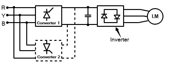
Ques 21. The pressure coil of a wattmeter consists of:
- More number of turns of the line wire✓
- Less number of turns of fine wire
- Less number of turns of thick wire
- More number of turns of thick wire
A wattmeter is generally used to measure the power in an A.C circuit. A wattmeter consists of two coils, one coil is called the current coil and another coil is called the pressure coil. The current coils are connected in series with the circuit, while the potential coil is connected in parallel. The coil represented with less number of turns between M and L is the current coil, which carries the current in the load and has very low impedance. The c with more number of turns between the common terminal and V is I pressure coil, which is connected across the load and has a high impedance. So in a wattmeter, the current coil act as an ammeter and the pressure coil as a voltmeter, and it displays a reading proportional to the power consumed which is the product of current and voltage

