Ques 22. The electrostatic instrument are suitable for the measurement of
AC and DC voltages✓
AC voltages and current
DC voltages and current
AC and DC currents
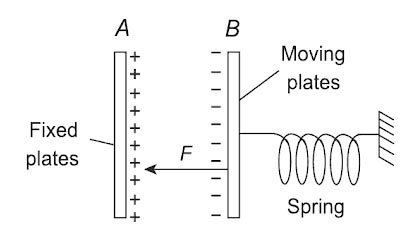
Electrostatic instruments are the only instruments that are directly voltage-sensitive and do not depend on a current for their operation. Basically, electrostatic instruments are all voltmeters. Practically such instruments may be used for the measurement of current and power but both the types of measurements require measurement o the voltage across a known impedance. The main advantage of such instruments is the measurement of high voltages in both a.c. and d.c. circuits without any errors due to eddy current losses and hysteresis.
The operation of all the electrostatic instruments is based on the principle that there exists a force between the two plates with opposite charges. This force can be obtained using the principle that the mechanical work is done is equal to the stored energy if there is a relative motion of plates.
In electrostatic instrument deflecting torque is proportional to
Where K = spring constant C = capacitance between the plate
Since the deflection is proportional to the square of the voltage to be measured, the instrument can be used on both ac and dc. The instrument exhibits a square-law response and hence the scale is nonuniform.
Advantages of Electrostatic Instrument
They can be manufactured with very high accuracy.
The instruments may be calibrated with d.c., and yet the calibration would be valid for a.c. also since the deflection is independent of the waveform of the applied voltage.
Since no iron is used for their construction, they are free from hysteresis, eddy current losses, and temperature errors.
Once the discs are charged, no more current is drawn from the circuit and the instrument represents infinite impedance.
Ques 23. Schering bridge is used to measure
Dielectric loss✓
The inductance
Low resistance
Mutual Inductance
The Schering Bridge is an electrical circuit used for measuring the insulating properties of electrical cables and equipment.It is also used for power factor measurement. It is an AC bridge circuit, developed by Harald Schering. It has the advantage that the balanced equation is independent of frequency.
In this diagram:
C1 = capacitor whose capacitance is to be determined, R1 = a series resistance representing the dielectric loss component in the capacitor C1, C2 = a standard capacitor, R3 = a variable non-inductive resistance, C4 = a variable capacitor, R4 = a non-inductive resistance in parallel with the variable capacitor C4.
The bridge is balanced by successive variations of R3 and C4 until the detector shows no deflection.
At balance C1 = C2R4/R3
Note:-
Maxwell bridge is used to measure the value of unknown inductance.
Heaviside bridge is used to measure mutual inductance in terms of a known self-inductance.
Ques 24. The ratio error in the current transformer is due to:
The power factor of primary
Wattless component of the current in the primary
Exciting current✓
Leakage flux
Exciting current is the current which flows through the transformer primary when the transformer is under no load. Even on a no-load, a small amount of current is drawn from the primary side, to set up the required magnetic flux in the magnetic core. This current is known as the “No Load Current” or magnetization current.
The no-load current is about 3-5% of the full load current and it accounts for the losses in a transformer.
In no-load conditions, only iron losses occur. Copper losses are zero in this condition as secondary current is zero and primary current is negligibly small.
Iron Loss (Pi)
The power loss in a transformer that takes place in its iron core is known as iron loss. In the transformer, flux set up in the core remains constant from no load to full load. Hence this power loss in a transformer is independent of load and is also known as constant losses of a transformer.
This power loss in a transformer has two components named hysteresis loss and eddy current loss. To determine the iron loss, an open circuit test of the transformer is performed.
Now coming back to the question………
Current transformers are used to perform two tasks. Firstly, they step down the heavy power system currents to low values that are suitable for the operation of the relays and other measuring instruments (meters) connected to their secondary windings.
Secondly, they isolate the relays and meters circuits from the high voltages of the power system. The standard current ratings of the secondary windings of the CTs.
CT Error
In practice, it is said that the current transformation ratio I2/I1 is equal to the tums ratio N1 / N2. But actually, it is not so. The current ratio is not equal to the turns ratio because of magnetizing and core loss components of the exciting current.
In ideal CT the secondary current is given as
${I_S} = \dfrac{{{I_P}}}{N}$
But in practical CT the ratio is
${I_S} = \frac{{{I_P}}}{N} – {I_O}$
Thus, the actual CT does not reproduce the primary current exactly in the secondary side both in magnitude and phase due to exciting current IO. The exciting current Io is the main source of errors in both measuring and Protective CTs. The error in magnitude is due to an error in CT ratio which is called “ratio error” and the error in phase is called “phase-angle error.”
Ratio error (current Error)
The actual transformation ratio (Na) is not equal to the rated (nominal) transformation ratio (N) since the primary current is contributed by the exciting current. The error introduced due to this difference in CT ratios is termed a ratio error or current error. The ratio error in percentage is expressed as
Ratio Error = (Nominal Ratio – Actual Ratio)/Actual ratio
The ratio error is largely dependent upon the value of the iron-loss component IC of the exciting current.
The ratio error is considered to be positive when the actual ratio of the CT is less than the nominal ratio, i.e., when the secondary current, for a given primary current, is high.
Ques 25. The major cause for creeping in energy meter is:
Overcompensation for friction✓
Vibration
Stray magnetic field
The excessive voltage across the potential coil
Creeping in the energy meter is the phenomenon in which the aluminum disc rotates continuously when only the voltage is supplied to the pressure coil, and no current flows through the current coil. In other words, the creeping is the kind of error in which the energy meter consumes a very small amount of energy even when no load is attached to the meter.
Creeping occurs due to
Overcompensation for friction.
The supply voltage is more than the normal voltage
Stray magnetic field
Vibration
To eliminate this, two holes are drilled in the disc 180° opposite to each other. When this hole comes under the shunt magnet pole, it gets acted upon by a torque opposite to its rotation. This restricts its rotation, under no-load conditions.
Ques 26. A 3-phase synchronous motor, connected to the infinite bus, is operating at no load at normal excitation. The field excitation of the motor is first decreased to zero and then increased in the reverse direction. The armature current of the synchronous motor will;
Remain constant
First decrease and then increase
Increase continuously✓
First increase and then decrease
Synchronous motor excitation refers to the DC supply given to the rotor which is used to produce the required magnetic flux.
Power Factor = Useful Power /Magnetizing or Apparent Power
The magnetizing power or current does not contribute to the active power and is purely reactive. Therefore, any electromagnetic device which draws excitation for its magnetic circuit from an AC system will have a lagging power factor.
Normal excitation– In this case, the synchronous machine gets the required flux through the DC voltage supplied. Hence the motor works on unity p.f.
Under excitation:– As field current reduces, the flux will start reducing, to keep this flux constant the armature draws high magnetizing current or lagging reactive VA from the bus. Hence in this case the motor is said to operate under a lagging power factor and the motor is said to be under-excited.
At zero field current, the motor acts as a synchronous reluctance motor. A reluctance motor is a synchronous motor with no field winding or Permanent magnet excitation at all. In this case, the magnetizing current is fully taken from the bus.
If we increase field current in the reverse direction to keep flux constant draws more currents. During this process, the load angle increases. At one point, the reverse field force dominates reluctance torque and rotor slips are pole pitch and align to the opposite pole. The instant angle aligns to the opposite pole the flux will be very high to reduce this flux current drop steeply to synchronous motor value. This torque is reluctance + synchronous motor torque.
or
The Back emf will go to zero when the field is reduced, so the Current input will be increased. But when the Field increases (though in the reverse direction) the back emf will cause the current to reduce.
Ques 27. If resistance is inserted in the rotor circuit of a slip ring induction motor, then compared to the direct line starting:
Both the starting current and torque reduce
Both the starting current and torque increase
The starting current reduces but starting torque increases✓
The starting current reduces but starting torque
Starting torque is directly proportional to the rotor resistance of an induction motor.
The resistance of the squirrel-cage induction motor cannot be varied as compared to the slip ring induction motor.
In the squirrel-cage induction motor, the rotor has very low fixed resistance, therefore, the starting torque is low due to the low power factor and high reactance.
In the SLIP RING induction motor the ends of the rotor windings are externally connected by a variable rheostat (resistance is varied in order to give it proper starting and running current).
So more the resistance, more the torque. When we add resistance to the rotor the torque is high, the slip is high and the current is reduced.
Therefore slip ring induction motor is used for providing high starting torque
Ques 28. Starting torque can be obtained in the case of a single-phase induction motor with identical main and auxiliary windings by connecting:
A capacitor across the mains
A capacitor in series with the machine
A capacitor in series with the auxiliary winding✓
Equal value capacitors in series with the main and the auxiliary windings
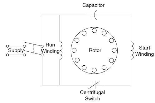
All single-phase induction motors have two stator windings, a main (running) winding and an auxiliary (starting) winding. If the two winding currents are shifted in time phase, a rotating field is created which is necessary for the production of starting torque. The time phase displacement between auxiliary winding current Ia and main winding current Im is obtained by putting the suitable capacitor in series with auxiliary winding.
Hence The capacitor increases the starting torque by producing a greater phase shift between the current in the run winding and the current in the start winding.
To increase the Power factor we can connect the capacitor in parallel.
Ques 29. If 2.2 m long conductor has a cross-sectional area of 0.025 m2 and resistance of 5 ohms, find its resistivity.
0.072 ohm m
0.057 ohm- m✔
0.58 ohm m
0.67 ohm m
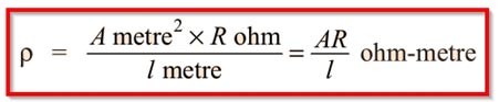
Resistivity ρ of a conductor is given by
ρ = (0.025 × 5)/2.2
ρ = 0.57 Ω-m
Ques 30. The distribution transformer has core losses:
More than the full load copper losses
Equal to full load copper losses
Less than the full load copper losses✓
Negligible compared to full load copper losses
Distribution transformers are used for lower voltage distribution networks as a means of end-user connectivity. (11kV, 6.6 kV, 3.3 kV, 440V, 230V) and are generally rated less than 200 MVA. Distribution transformers depend on the typical load cycle for which it has to supply power.
Consider a distribution transformer, the load(secondary side) may be connected or disconnected according to the consumer. But the distribution transformer would be continuously energized from the supply(feeders) as the load is unexpected(we don’t know at what time the load is connected or disconnected).
Such transformers, therefore, are designed to have minimum core losses. Whereas power transformer is designed to have minimum copper losses
Ques 31. Hollow conductors are used in the transmission lines to
Improve heat dissipation
Reduce corona loss✓
Reduce skin effect
Reduce the line inductance
The size of the conductor and their spacing have a considerable effect on corona loss.
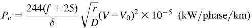
Corona loss is given by
Where, f = Supply frequency
δ = Air density factor
r = Radius of the conductor
D = Distance between the conductors
V = Operating voltage of the transmission line
Vo = Critical disruptive voltage
Corona loss increases with frequency. Corona loss increases very fast with an increase in system voltage since the loss is dependent on (V – Vo)2
Since the formation of corona on the conductor surface is dependent upon the maximum gradient, With an increase in the conductor size Diameter the potential gradient is decreased
By increasing conductor size the voltage at which corona occurs may be raised.
A hollow conductor increases the effective diameter without using any extra material. Therefore corona effect gets reduced.
Corona loss can be minimized by controlling the following factors:
The frequency of supply: Corona loss increases as the supply frequency increases.
The radius of the conductors: Generally corona loss increases when decreasing the radius of the conductor. In order to prevent this, bundled or hollow large diameter conductors must be used.
The distance between the two conductors: To prevent corona spacing between the conductors must be increased.
Air Pressure: In hilly areas, the corona effect is more dominant due to reduced pressure.
Using Smooth conductor: Since corona loss is higher at sharp corners of the conductors, due to the presence of the highly non-uniform field, increasing the conductor radius as a whole can reduce the corona effect significantly. More the imperfections on the conductor surface will be Corona.
Ques 32. In a junction transistor, the doping level of the collector region is
Higher than the emitter region
Lower than the base region
Is higher than the base region but lower than the emitter region✓
Independent of the doping of base-emitter regions
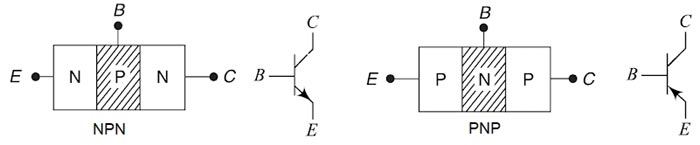
A transistor has three doped regions, as shown in Fig. Notice that for both types, the base is a narrow region sandwiched between the larger collector and emitter regions.
Usually, the emitter-base junction is forward biased and the collector-base junction is reverse biased and also termed an Active Region. In this type of connection Transistor work as an amplifier.
The emitter region of a transistor is heavily doped. Its job is to emit or inject current carriers into the base.
The base region is very thin and lightly doped. Most of the current carriers injected into the base from the emitter do not flow out the base lead. Instead, most of the current carriers injected into the base pass on to the collector.
The collector region is moderately doped and is the largest of all three regions.
The collector region attracts the current carriers that are injected into the thin and lightly doped base region. Incidentally, the collector region is the largest of all three regions because it must dissipate more heat than the emitter or base