Ques 44. The deflection torque can be produced by:
Gravity control
Spring control
Air friction✓
Magnetically
In order to move the pointer from its zero position on the scale deflecting torque is required.
The pointer is made to move because of a force or a torque produced. This deflecting torque can be produced by any of this effects of current (or of voltage) such as
Magnetic effect
Electrostatic effect
Electromagnetic effect
Thermal effect
Chemical Effect
The deflecting torque works on the moving system to which the pointer is attached. Obviously, the magnitude of deflecting torque produced is proportional to the magnitude of the quantity being measured, say, the current I flowing through the instrument. A deflecting torque is required to overcome the inertia, damping effect, and controlling effect of the moving system.
Note:-
Spring control and gravity control are used for controlling torque.
With the help of the deflecting torque, the pointer deflection will take place on the calibrated scale but to stop the pointer at the definite position, controlling torque (Tc.) comes into action. As the deflection of the pointer increases, the controlling torque also increases and stops the pointer at the measured value.
Controlling torque is also known as restoring torque i.e., it brings back the pointer to its zero position when deflecting torque is withdrawn. The pointer attains a steady position when controlling torque becomes numerically equal to deflecting torque i.e., Tc = Td
Air friction is used in damping torque.
At the final deflected position, when the deflecting and controlling torques are equal, the pointer starts oscillating owing to its inertia and therefore, cannot immediately settle at its final deflected position. If no extra force is provided to dampen these oscillations, the mooing system will take considerable time before coming to settle to the final deflected position. This is especially undesirable if the number of readings to be taken is quite large.
Other e.g of damping torque are:
Eddy current damping, Hydraulic damping
Ques 45. Carbon brushes are used in electric motors to:
Brush off carbon deposit on the commutator
Provide a path for the flow of current✓
Prevent overheating of the armature winding
Prevent sparking during commutation
We know that commutator is connected to the armature so as the armature is rotating (to cut the flux in order to induce the EMF ) obviously commutator will also rotate with the armature.
So in order to collect the current, we should have something which is stationary and can be fit into the commutator, and that is brushes.
The number of brushes depends on how much current we need to tap from the commutator.
Brushes are made up materials like carbon, copper, and graphite.
Copper brushes are used for the machine designed for large currents at low voltage.
Graphite and Carbon Graphite are self-lubricated and therefore widely used.
Ques 46. LVDT is a
Displacement transducer✓
Velocity transducer
Acceleration transducer
Pressure transducer
Linear Variable Displacement Transducer (LVDT)
Displacement is a vector quantity representing a change in the position of a body or a point with respect to a reference. It can be linear or angular (rotational) motion. With the help of a displacement transducer, many other quantities, such as force, stress, pressure, velocity, and acceleration can be found. In the case of linear displacement, the magnitude of measurement may range from a few micrometers to a few centimeters. A majority of displacement transducers detect the static or dynamic displacement by means of suitable mechanic links coupled to the point or body whose displacement is to be measured.
The main electrical displacement transducers work on the principle of:
Variable resistance: transducer is the strain gauge.
Variable inductance: transducer is linear variable differential transform
Variable capacitance:: transducer is the parallel plate capacitor with the variable gap
Synchros and resolver: Used to measure angular displacement
Ques 47. Base Impedance of the power system is given by
Per unit system of any quantity can be defined as:
Quantity in per unit= (actual quantity)/(base value of quantity)
There is a relation between these quantities, viz:
kilovolt amperes(KVA),
Kilovolt (KV),
current (I)
impedance (Z).
Base current, A= (base KVA(1ϕ))/(base voltage,KV(LN))….(1)
Base impedance, Ω= (base voltage, V(LN))/(base current, A)….(2)
But from equation (1), base current has been defined and we can substitute the value in equation(2)
So that Base impedance=(base voltage, V(LN))/((base KVA(1ϕ))/(base voltage, KV(LN)))
Base impedance = base voltage, V(LN)× (base voltage, KV(LN))/(base KVA(1ϕ))….(3)
The prefix K stands for kilo and has an equivalent value of 1000. When you multiply K by a quantity, you must divide the quantity by 1000 because by multiplying by K, you have multiplied the quantity by 100 and as such, you must divide by 1000 to counteract the K.
From equation (3) above, we can manipulate it to give us a form that we can easily use in solving problems.
Ques 48. The process of converting A.C into D.C is called
Amplification
Modulation
Rectification✓
Factorization
Rectification is any process that converts a bidirectional flow into a unidirectional flow.
or
Rectification is a process by which an alternating current is made usable for a direct current requirement. Thus, by rectification, alternating current is converted to direct current using equipment known as a rectifier
Modulation is a process through which audio, video, image, or text information is added to an electrical or optical carrier signal to be transmitted over a telecommunication or electronic medium.
Factorization is the decomposition of an object (for example, a number, a polynomial) into a product of other objects, or factors, which when multiplied together give the original.
Ques 49. One advantage of transformer coupling in a transistor amplifier is that:
It provides an excellent frequency response
It is simple and less expensive than others
The low power supply may be used
High efficiency and high power output is obtained✓
Before coming to the question you must know the impedance matching.
According to the “Maximum power transfer theorem“, maximum power is transferred only when the impedance at the source is equal to the impedance at the load.( In simple terms, Impedance is to AC what Resistance is to DC). By using a transformer between the load and the supply, their impedance can be matched and maximum power will be transferred.
Now coming back to the question:
When the output voltage of a transistor amplifier is coupled to another transistor through a transformer the amplifier is known as a transformer-coupled amplifier.
The main advantages of the coupling Network are it passes a c. signal from one stage to the next and block the passage of dc. the voltage from one stage to the next.
Advantages and Disadvantages of Transformer Coupled Amplifiers
Advantages:
No signal power is lost in the collector or base resistors.
An excellent impedance matching can be achieved in a transformer-coupled amplifier.
Due to excellent impedance matching, transformer coupling provides higher gain.
D.C isolation between first and second stages.
Disadvantages:
It has a poor frequency response.
The coupling transformers are bulky and fairly expensive at audio frequencies.
The frequency distribution is higher i.e. low-frequency signals are less amplified as compared to the high-frequency signals.
Transformer coupling tends to introduce him in the output.
Cost is also more.
Applications of Transformer Coupled Amplifier
These are mostly employed for impedance matching.
These are used as driver amplifiers sometimes used as an output amplifiers.
Ques 50. A single binary digit is called
Byte
Bit✓
Data
Logic
A bit (short for binary digit) is the smallest unit of data in a computer. A bit has a single binary value, either 0 or 1.
Whereas, A group of binary digits or bits (usually eight) operated as a unit
Ques 51. Kelvin is the SI unit of:
Time
Current
Tempreature✓
Light Intensity
Kelvin is the SI unit of Tempreature
.
Ques 52. According to Ohm’s Law
The voltage is constant to current
The voltage is proportional to the current✓
Voltage is inversely proportional to the current
The voltage is proportional to the resistance
Ohm’s law states that the electric current flowing through the conductor is directly proportional to the potential difference between its two ends when the temperature and other physical parameters of the conductor remain unchanged.
Ques 53. The unit of reluctance is
Ampere-turns
Ampere-turn/meter
Ampere-turn/Weber✓
It is dimensionless
Reluctance is defined as
ℜ = F/Φ
F = magnetomotive force (MMF) in ampere-turns
Φ = the magnetic flux in webers.
Therefore the unit of Reluctance is ampere-turns per Weber ( AT/Weber) (a unit that is equivalent to turns per Henry)
Ques 54. The minus sign in the expression e = -Ndφ/dt is due to
Fleming’s Rule
Thumb’s Rule
Faradays’s Law
Lenz’s Law✓
Electromagnetic induction is the process by which a current can be induced to flow due to a changing magnetic field.
The principle of electromagnetic induction state that if an electrical conductor is exposed to a changing magnetic field (magnetic lines of flux, a voltage will be induced into that conductor.
e = -Ndφ/dt
The negative sign in the above expression is due to Lenz’s Law.
Faraday’s law tells us the magnitude of the EMF produced, whereas Lenz’s law tells us the direction the current will flow.
So according to Lenz’s Law
The magnetic field produced by an induced current always opposes any changes in the magnetic flux. In other words, Effect Opposes the Cause. Here the effect is induced current and the cause is changing magnetic flux.
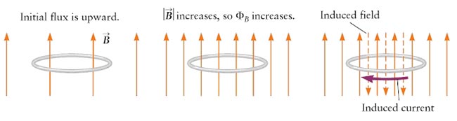
Let’s apply Lenz’s law to an arrangement in which the magnetic field passes through a metal loop with the field initially directed upward through the loop. We also suppose the magnitude of field B increases with time.
Here, B is perpendicular to the plane of the loop, so there is a magnetic flux directed upward through this surface. The magnitude B is increasing with time, so φB is also increasing. This changing flux produces an induced emf, so there will indeed be an induced current in the loop. According to t Lenz’s law, the magnetic field produced by this induced current must oppose the change in flux, so the induced magnetic field must be downward.