
Ques 55. When XL is equal to XC than
- Z = R✓
- Z = Xc
- Z = Xl
- None of these
In RLC series circuit the total impedance of the series LCR circuit is given as Z2 = R2 + (X1 – X2)2 where X1 is inductive reactance and X2 is capacitive reactance. At a particular frequency (resonant frequency), we find that X1=X2 because the resonance of a series RLC circuit occurs when the inductive and capacitive reactances are equal in magnitude but cancel each other because they are 180 degrees apart in phase. Therefore, the phase angle between voltage and current is zero and the power factor is unity. Thus, at the resonant frequency, the net reactance is zero because of X1=X2. The circuit impedance Z becomes minimum and is equal to the resistance R. “Since the impedance is minimum, the current will be maximum”.
Ques 56. The following statement is associated with Buchholz relay is not true
- It is a gas actuated device
- It is a current operative device✓
- It is placed between the transformer tank and the conservator
- It causes alarm for minor fault and tripping for major fault
The Buchholz relay is a gas-operated relay used for the protection of oil-immersed transformers against all types of internal faults. The slow-developing faults called incipient faults in the transformer tank below oil level operate Buchholz relay which gives an alarm. If the faults are severe it disconnects the transformer from the supply. It uses the principle that due to the faults, oil in the tank decomposes, generating the gases. The 70% component of such gases is hydrogen which is light and hence rises upwards towards the conservator through the pipe. The Buchholz relay is connected to the pipe, as shown in Fig. Due to the gas collected in the upper portion of the Buchholz relay, the relay operates and gives an alarm. There are many types of internal faults such as insulation fault, core heating, bad switch contacts, faulty joints, etc. which can occur. When the fault occurs the decomposition of oil in the main tank starts due to which the gases are generated. As mentioned earlier, the major component of such gases is hydrogen. The hydrogen tries to rise up towards the conservator but in its path, it gets accumulated in the upper part of the Buchholz relay. When gas gets accumulated in the upper part of the housing, the oil level inside the housing falls. Due to this the hollow float tilts and closes the contacts of the mercury switch attached to it. This completes the alarm circuit to sound an alarm. Due to this operator knows that there is some incipient fault in the transformer. The transformer is disconnected and the gas sample is tested. The alarm circuit does not immediately disconnect the transformer but gives the only indication to the operator. This is because sometimes bubbles in the oil circulating system may operate the alarm circuit though there is no fault. However, if a serious fault such as an internal short circuit between phases, earth fault inside the tank, etc. occurs then a considerable amount of gas gets generated. Thus due to the fast reduce the level of oil, the pressure in the tank increases. This energizes the trip circuit which opens the circuit breaker. Thus transformer is totally disconnected from the supply. The connecting pipe between the tank and the conservator should be as straight as possible and should slope upwards the conservator at a small angle from the horizontal This angle should be between 10 to 11° For the economic considerations, Buchholz relays are not provided for the transformers having a rating below 500 kVA. Advantages The various advantages of the Buchholz relay are, Normally a protective relay does not indicate the appearance of the fault. It operates when a fault occurs. But Buchholz relay gives an indication of the fault at the very early stage, by anticipating the fault and operating the alarm circuit. Thus the transformer can be taken out of service before any type of serious damage occurs. It is the simplest protection in the case of transformer. Limitations The various limitations of the Buchholz relay are,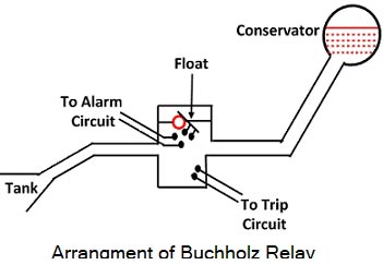
Ques 57. Which of the following is a vector quantity
- Volume
- Speed
- Density✓
- Acceleration
Ques 58. Electrical fault between two windings of the same phase of a generator having double star winding can be detected by the following protection in the generator
- Short circuit fault
- Earth fault protection
- Inter turn fault protection✓
- Overvoltage protection
The Merz-Price protection system gives protection against phase to phase faults and earth faults. It does not give protection against inter-turn faults. The inter-turn fault is a short circuit between the turns of the same phase winding. Thus the current produced due to such fault is a local circuit current and it does not affect the currents entering and leaving the winding at the two ends, where C.T.s are located. Hence Merz-Price protection cannot give protection against inter-turn faults. In a single turn generator, there is no question of inter-turn faults but in multiturn generators, the inter-turn fault protection is necessary. So such inter-turn protection is provided for multiturn generators such as hydroelectric generators. These generators have double winding armatures. This means each phase winding is divided into two halves, due to the very heavy currents which they have to carry. This splitting of the single-phase winding into two is advantageous in providing inter-turn fault protection to such hydroelectric generators. The scheme uses the cross-differential principle. Each phase of the generator is doubly wound and split into two parts S1 and S2 as shown in Fig.. The current transformers are connected in the two parallel paths of each phase winding. The secondaries of the current transformers are cross-connected. The current transformers work on circulating the current principle. The relay is connected across the cross-connected secondaries of the current transformers. Under normal operating conditions, when the two paths are sound then currents In the two parallel paths S1 and S2 are equal. Hence currents in the secondaries of the current transformers are also equal. The secondary current flows around the loop and Is the same at all the points. Hence no current flows through the relay and the relay is inoperative. If the short circuit is developed between the adjacent turns of the part Sit of the winding say then currents through S1 and S2 no longer remain the same. Thus unequal currents will be induced in the secondaries of the current transformers. The difference between these currents flows through the relay R. Relay then closes its contacts to trip the circuit breaker which isolates the generator from the system. Such an inter-turn fault protection system is extremely sensitive but it can be applied to the generators having doubly wound armatures.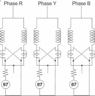
Ques 59. The induction generator is stable at a
- Speed below synchronous speed
- Speed above synchronous speed✓
- Speed equal to synchronous speed
- None of these
An induction generator or asynchronous generator is a type of alternating current (AC) electrical generator that uses the principles of induction motors to produce power. if the rotor is accelerated to the synchronous speed then, the slip will be zero and hence the net torque will be zero.
If the rotor is made to rotate at a speed more than the synchronous speed, the slip becomes negative. A rotor current is generated in the opposite direction, due to the rotor conductors cutting the stator magnetic field.
In generator operation, a prime mover (turbine or engine) drives the rotor above the synchronous speed (negative slip). The stator flux still induces currents in the rotor, but since the opposing rotor flux is now cutting the stator coils, an active current is produced in stator coils and the motor now operates as a generator, sending power back to the electrical grid.
Ques 60. Corona loss is less when the shape of the conductor is
- Circular✓
- Flat
- Oval
- Independent of shape
Frequency of supply: Corona loss increases as the supply frequency increases.
Radius of the conductors: Generally corona loss increases on decreasing the radius of the conductor.
In order to prevent this, bundled or hollow large diameter conductors must be used.
Distance between the two conductors: To prevent corona spacing between the conductors must be increased.
Air Pressure: In hilly areas, the corona effect is more dominant due to reduced pressure.
Profile of conductor. The electric field around a conductor depends on the shape of the conductor. If the conductor is round, the field will be uniform around the conductor but if it it flat or oval, the field will be more at sharp ends. Thus corona loss in cylindrical conductors will always be less compared to any other shapes.
Ques 61. Which of the following combination of 3-phase transformers can be successfully operated in parallel
- Δ − Y and Δ − Y✓
- Y − Y and Δ − Y
- Δ − Δ and Δ − Y
- Y − Δ and Δ − Δ
One condition of parallel operation of the transformer is to have the same phase shift i.e The transformers should have zero relative phase displacement between the secondary line voltages This condition indicates that the two secondary line voltages should have zero phase displacement which avoids unintended short circuits between the phases of two windings. In star/star and delta-delta connections, the line voltages and currents are in phase opposition like single-phase transformers. So the phase shift will be zero. Star/delta connection: For star delta connection there is a phase shift of ± 30°. i.e either the star voltage leads the delta voltage by 30° or the star voltage lags the delta voltage by 30° Delta/Star connection: Similarly in the Delta star connection there is a phase shift of ± 30°. i.e either the delta voltage lags the star voltage by 30° or the delta voltage leads the star voltage by 30°. Here the 2nd condition of parallel operation should also be considered i.e the two transformers must have the same phase sequence. Now if the phase sequence is kept constant then in Star/delta connection the star voltage will lead the delta voltage by 30° and for delta-star connection, the delta voltage will lag the star voltage by 30°. Therefore total phase shift will be + 30° – 30° = 0. Therefore, option 1 is correct.Phase shift
Ques 62. For very low speed and high power applications, the best suited A.C Motor is
- Slip-Ring Induction motor
- Squirrel Cage Induction motor
- A.C commutator Motor
- Synchronous Motor✓
Note:- AC commutator motors, like comparable DC motors, have higher starting torque and higher speed than AC induction motors.
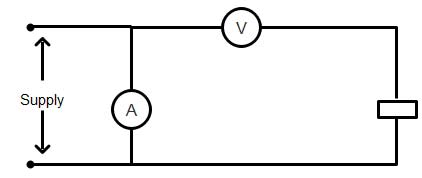
Ques 63. By mistake voltmeter and Ammeter are connected as shown in the figure
- Only voltmeter will burn away
- Only ammeter will burn away✓
- Both voltmeter and ammeter will burn away
- None will burn away
As we know that Ammeter is always connected in series with the element through which the current is to be measured. The figure below shows two cases, in one case ammeter is connected in series while in the other case, an ammeter is connected in parallel. As an Ammeter has a very low internal resistance, therefore, the ammeter is connected in series so that all the current flowing in the circuit elements must flow through the ammeter in order for it to measure the current. The voltmeter is always connected in parallel to the element across which potential difference i.e. voltage is to be measured. If an ammeter is a connected parallel to the load, and as in a parallel path current gets divided. The maximum part of the current will prefer flowing through ammeter as it has less resistance. The magnitude of current being so high will lead to ammeter being burnt or blown. And this phenomenon is what we call a short circuit. Let’s take an example when the voltage is 20V and the resistance of the load is 10ohms, the current generated ( assuming ammeter resistance to be 0.5 ohms) is 40A. While your ammeter could ideally measure 2 A. Your ammeter would be designed to handle such low values while this connection will yield 20 times more current that your ammeter will not be able to handle anyhow and will result in a short circuit. Voltmeter ideally has an infinite internal resistance, practically a large enough resistance. So if connected in series, a very small current will flow or no current will flow.
Ques 64. A 100 turns coil has an inductance of 6 mH. If the number of turns is increased to 200, all other quantities remain the same, the inductance will be
- 24 mH✓
- 12 mH
- 3 mH
- None of these
Inductance in the solenoid is given as L =μoN2A/l Where μο =vacuum permeability = 4π x 10-7 wb/m N = Number of turns A = area of cross-section l = length of the solenoid L =(μoN2πr2)/l Now if the number of turns is doubled and all the other parameter are kept constant than the inductance become four times i.e 6 x 4 = 24mH
Ques 65. A light-emitting diode can be made from
- Phosphorescent material
- Germanium
- Silicon
- Gallium arsenide✓

