
DMRC Junior Engineer Previous Year Electrical Question Paper with explanation and Solution -2014
Ques 1. In a three-phase induction motor, the rotor field runs at the following speed with respect to the stator structure:
- At synchronous speed in the direction of the stator field✓
- At a slip speed in the direction of stator speed
- At synchronous speed in a direction opposite to that of stator field
- At zero speed
As we know that the Rotor frequency is slip times the stator frequency i.e fr = sf Where fr = Rotor frequency and f = stator frequency When three-phase currents are supplied to the staler winding of a polyphase induction motor, a resultant field is set up which rotates at a constant speed called synchronous speed (Ns= 120f/P). This rotating field induces poly phase e.m.fs. in the rotor winding and if rotor winding is closed, polyphase currents circulate in it. These currents set up a revolving field in the rotor which rotates at a speed Nr Now, Nr=120f/P with respect to the rotor. 120 x Sf/P = SNs When the rotor itself is rotating at a speed N r.p.m. in the space. Speed of rotor field in space = N + Nr =( 1 − S)Ns + SNs = Ns − SNs + SNs = Ns Thus, the rotor magnetic field also rotates, in space, at the same speed, and in the same direction as that of the stator field. Hence, the two fields are magnetically locked with each other and are stationary with respect to each other. Thus, we find that even though the rotor is not rotating at synchronous speed, the rotor field rotates a the synchronous speed. In fact, the rotor field remains locked with the stator field, irrespective of the rotor speed. An induction motor generates its own rotor current by an induced voltage from the rotating magnetic field of the stator. The current is induced in the windings of the rotor as it cuts, through the magnetic flux lines of the rotating stator field. So the magnetic field of the stator always attracts the magnetic field of the rotor. Hence the rotor begins to turn in the same direction as the rotating magnetic field.
Ques 2. V/f is maintained constant in the following case of speed control of induction motor:
- Below base speed with voltage control
- Below the base speed with frequency control✓
- Above base speed with frequency control
- None of these
An induction motor on a normal supply operates with a rotating field set up by three-phase currents in the stator winding. The magnitude of the field is controlled broadly by the voltage impressed upon the winding by the supply. This is because the resistance of the winding results in only a small voltage drop, even at full-load current, and therefore in the steady-state the supply voltage must be balanced by the e.m.f. induced by the rotating field. This e.m.f. depends on the product of three factors: Synchronous speed, therefore, the motor speed can be controlled by varying supply frequency. The voltage induced in the stator is proportional to the product of supply frequency and air-gap flux. If stator drop is neglected, the terminal voltage can be considered proportional to the product of frequency and flux. V = φF And also the torque of an induction motor is directly proportional to the flux T ∝ φ ∝ V/F Hence for the same design parameters [φ remaining the same] and ratio V/F, the torque of the motor, T, will remain constant. Since both V and f, are functions of the supply system, a variation in V and f can alter the performance and the speed-torque characteristics of a motor as required, at constant torque. Increased Voltage If in the steady-state, the voltage applied to the stator terminals is increased without a corresponding increase in the frequency, only the flux can vary to regain the balance between applied voltage and e.m.f. If the flux is forced to increase by applying excessive voltages, the iron core of the machine is driven progressively into saturation. This not only increases iron losses due to hysteresis and eddy currents but can lead to a very marked increase in stator current, with corresponding resistive losses. Since most machines are designed to work with the minimum of material, their magnetic circuits are normally very close to saturation and excessive stator voltage is a condition that must be carefully avoided. Reduce frequency Any reduction in the supply frequency, without a change in the terminal voltage, causes u increase in the air-gap flux. Induction motors are designed to operate at the Knee point of the magnetization characteristic to make full use of the magnetic material. Therefore, the increase in flux will saturate the motor. This will increase the magnetizing current, distort the line current and voltage, increase the core loss and the stator copper low, and produce a high-pitch acoustic noise. Base Speed Base speed,” is defined as the speed at which the motor will first produce its maximum designed power output, and “maximum speed,” the fastest the motor can spin while producing that same amount of power (available torque falls off as speed increases past “base speed.”) Operation above base speed First, operation above base speed is easily achieved by increasing the output frequency above the normal mains frequency since the rise in the applied voltage which is not permissible beyond the rated voltage and has already been attained by reaching the rated speed. The speed beyond the rated is therefore obtained by raising the supply frequency alone and maintaining the voltage at constant as its rated value. Since V is constant above base speed, the flux will fall as the frequency is increased after the output voltage limit is reached. The machine flux falls in direct proportion to the actual V/f ratio. Although this greatly reduces the core losses, the ability of the machine to produce torque is impaired and less mechanical load is needed to draw full-load current from the inverter. The drive is said to have a constant power characteristic above base speed. Many applications not requiring full torque at high speeds can make use of this extended speed range. Operation below base speed Each AC induction motor is designed to run at a particular RPM, called base speed. When power is applied, the motor accelerates from 0 RPM. As it does, the torque remains constant and the horsepower increases until the base speed is reached. Above base speed, the torque falls off while the horsepower remains constant. Below the base speed (V/F ratio is maintained constant, except at low frequencies where (V/f ) ratio is increased to keep maximum torque constant. By maintaining a constant ratio of voltage to speed, we can maintain a constant air gap flux. Because torque is proportional to air gap flux, hence by constant V/f ratio, the torque can be made independent of speed in an AC motor. Hence we can achieve constant torque down to very low speeds. Example One example is a paper winder. When it begins to wind, the empty core is light and does not require much torque to turn. Therefore, it can be turned above base speed at reduced torque. As the roll is being wound and becomes heavier, the torque required to turn it becomes greater. Therefore, it is necessary for the drive to slow the speed and eventually run below the base speed so that torque is increased to handle the load. Eventually, the roll is heavy and requires the motor to provide maximum torque.
and φ = V/F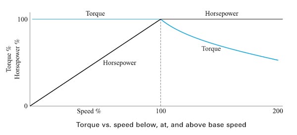
Ques 3. In a double-cage induction motor, which of the following is not true:
- The resistance of the outer bar is less✓
- Leakage inductance of outer cage is less
- The outer bar has the smaller cross-section
- None of these
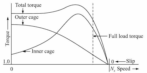
As we know that the induction motor requires high rotor resistance for good starting torque but low rotor resistance for good running performance. In a squirrel cage motor, the rotor windings are permanently shorted and so it is not possible to increase the roto resistance at starting. However, the double cage motor overcomes this difficulty: it has the same type of stator as other cage motors but only the rotor construction is different. The rotor has two sets of slots-one set close to the rotor periphery and the other buried deep inside the rotor as shown in Figure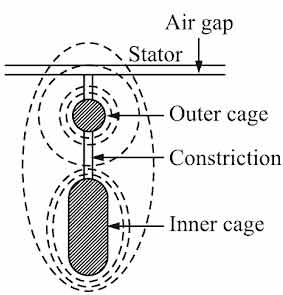
Ques 4. The voltage regulation of a transformer at full load 0.9 p.f. lagging is 5%. For a full load at 0.9 p.f. loading, it will :
- Remain the same
- Become negative
- Reduce and may even become negative✓
- Increase
Voltage regulation of a transformer is defined as the change or difference in the secondary voltage from no load to full load at a given power factor with the same primary voltage for both conditions, i.e., rated load and no load. It is generally expressed as a percentage of the full load value. ${\text{Voltage Regulation = }}\dfrac{{{E_{{\text{2 no – load}}}} – {V_{{\text{2 full – load}}}}}}{{{V_{{\text{2 full – load}}}}}}$ Voltage regulation depends on the voltage drop and the impedance of the transformer, load current, and load power factor. For lagging power factor load the secondary voltage decreases with an increase in the load current (when the transformer is loaded). Thus for lagging power factor loads, the regulation is positive ( voltage drop observed as the load current increases). For the leading power factor load, the secondary voltage increases slightly with an increase in the load current. Thus for leading power factor loads, the regulation is negative (raise in voltage as load current increases). Hence for the leading power factor voltage regulation decrease and may even become negative
Ques 5. For which of the following pair of machines, the stator, and its winding can be of the same type:
- Universal motor and stepper motor
- D.C. motor and hysteresis motor
- Hysteresis Motor and Reluctance Motor✓
- Induction motor and D.C. motor
Motors both single-phase and three-phase can be built with no dc excitation on the rotor and having non-uniform air-gap reluctance. The rotor does not have any windings. The stator of such motors will have windings similar to induction motor winding but the magnetic reluctance along the air gap will be made variable. Such induction motors when built as three-phase motors are called synchronous induction motors. Single-phase induction motors built with a variable air-gap reluctance and with having no dc supply on the rotor are called reluctance motors. Such motors start as induction motors but are pulled into synchronous speed because of the variation in air-gap reluctance. A hysteresis motor is a single-phase synchronous motor without any projected poles and without d excitation. Hysteresis motors start by virtue of the hysteresis losses induced in the rotor by the rotating magnetic field produced by the stator windings. The rotor of the hysteresis motor does not have any winding. The stator windings are made up of distributed windings in order to have a sinusoidal space distribution of flux. The stator windings can be either single or three-phase. In single-phase motors, the stator windings are customarily permanent-split-capacitor type. Hence like induction motor the reluctance motor and hysteresis motor can be built with either single-phase or 3 phase. There is a basic difference between hysteresis motor and reluctance motor. The reluctance motor starts as a single-phase induction motor and the rotor pulls into synchronism under favorable conditions. In a hysteresis motor, any load gets synchronized with stator poles provided hysteresis torque is able to accelerate it. Hence, in a reluctance motor, there is a tendency for the rotor to oscillate before synchronism, but in a hysteresis motor, the rotor and stator poles lock with each other without any oscillation.
Ques 6. In which of the following amplifier configurations the power gain ls the largest?
- Common Emitter✓
- Common-Collector
- Common-Base
- None of these
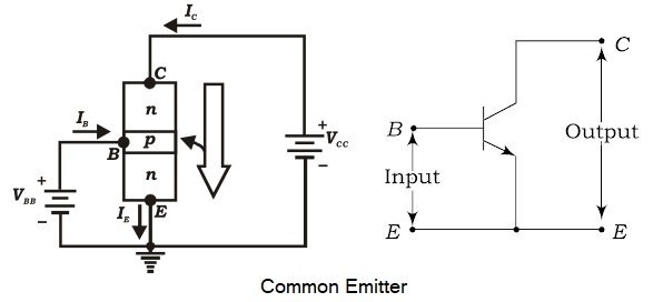
Out of the three transistor connections, the common-emitter circuit is the most efficient. It is used in about 90 to 95 percent of all-transistor applications. The main reasons for this are : In a common emitter connection, Ic is the output current and IB is the input current. The collector current here is expressed as: Ic = βIB + ICEO As the value of β is very large, therefore, the output current IC is much more than the input current IB. This increases the current gain effectively. The current gain of CE arrangement ranges from 20 to High Voltage and Power Gain As we have seen above, CE arrangement has a high current gain. This in turn, increases the voltage and power gain of CE circuit. In comparison to CB and CC circuits, the common emitter connection has the highest voltage and power gain. For this reason, the CE transistor connection is often used for amplifying purposes.
Where β = Current Gain
ICEO = Collector-Emitter current
500.
Ques 7. The transformer core is laminated in order to:
- Decrease copper losses
- Decrease entire core losses
- Decrease Only eddy current losses ✓
- Decrease only hysteresis losses
Eddy-current loss occurs whenever the core material is electrically conductive. It is the heat dissipation caused by the eddy current le flowing through the core resistance R (can be calculated by Ie2R). Since power is proportional to the square of the applied voltage in a circuit, i.e., P = V2/R while the induced voltage is proportional to fB, the eddy-current losses are proportional to f2B2, while B itself is related to the size of the loop. To reduce the eddy-current loss, a laminated core (consists of a stack of thin slices instead of a solid core) is used. The eddy-current loss is inversely proportional to the square of the number of laminations. To further reduce the eddy-current loss, an iron dust core that divides up the iron into fine particles (to prohibit the eddy-current flow) is invented, where the iron is ground into a powder, mixed with some insulating binder or matrix material, and then fired to produce a core shape. Such a core can operate at several MHz, but its permeability is lower than a solid iron. In a transformer, the eddy current loss is proportional to the square of the diameter of the core. Larger the diameter, the more the eddy current loss. Hence transformer core is laminated so that the net effective diameter of the transformer core reduces and thus eddy current loss can be minimized Hysteresis and eddy-current losses are collectively known as core losses.
Ques 8. For increasing the range of the voltmeter, one should connect
- The high value of resistance in series with the voltmeter✓
- Low-value resistance in series a with the voltmeter
- High-value resistance in parallel with the voltmeter
- Low-value resistance in parallel with the voltmeter
Voltmeters are connected in parallel with a part of a circuit. This is necessary because objects in parallel experience the same potential difference. The ideal voltmeter should have infinitely large – resistance so that no current flows through it. Any current flowing through a voltmeter means an increase in the total circuit current which will increase in the total circuit current. To increase the range of the voltmeter the series multiplier or we can say series resistance is connected with the voltmeter because if we connect the resistance in parallel the effective resistance will decrease which is not required in the case of the voltmeter
Ques 9. To conduct the Sumpners test on a transformer
- Only one transformer is sufficient
- Two identical transformers are needed✓
- Two unidentical transformers are needed
- At least three transformers are necessary
Sumpner’s test is another method of determining efficiency, regulation, and heating under load conditions. The O.C. and S.C. tests give us the equivalent circuit parameters but cannot give heating information under various load conditions. The Sumpner’s test gives heating information also. It can be compared with the back-to-back test, used for D.C machines(Hopkinson’s test), power consumption would be equal to the no-load power consumption of machines/ equipment. In O.C test, there is no load on the transformer while in S.C circuit test also only fractional load gets applied. In all O.C. and S.C. tests, the loading conditions are absent. Hence the results are incomplete. In Sumpner’s test, actual loading conditions are simulated hence the results obtained are much more accurate. Thus Sumpner’s test is a much-improved method of predetermining regulation and efficiency than the O.C. and S.C. tests. The Sumpner’s test requires two identical transformers. Both the transformers are connected to the supply such that one transformer is loaded on the other. We need two identical transformers because Often in large distribution substations, you are required to have two or more transformers running in parallel to accommodate the required peak load.
Ques 10. Unit of Reactive power is
- Watt
- Kilo-watt
- Var✓
- Volt-Ampere
Active power, P, or real power: watt (W) Reactive power exists in an AC circuit when the current and voltage are not in phase.
Reactive power, Q: volt-ampere reactive (var)
Complex power, S: volt-ampere (VA)
Apparent power, |S|: the magnitude of complex power S: volt-ampere (VA)

