
Ques 41. The type of turbine used in the hydro-electric plant for a water head range of 70 meters to 500 meters is
- Kaplan
- Propeller
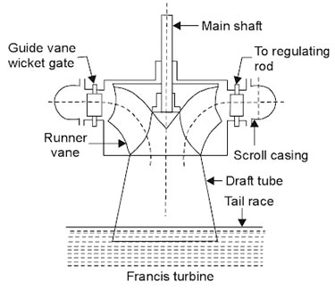
- Francis✓
- Pelton
Turbines are classified as given below: The inward flow reaction turbine having radial discharge at the outlet is known as the Francis turbine, after the name of J.B. Francis an American engineer who at the beginning designed an inward radial flow reaction turbine. The flow of water in the turbine may be radially from outward to inward or from inward to outward. but in both cases, the flow passing through the runner has the velocity component in a plane normal to the axis of the runner. In modern Francis, turbine water enters the runner of the turbine in the radial direction at the outlet and leaves in the axial direction at the inlet of the runner. Thus the modern Francis turbine is a mixed now type of turbine in which water enters radially at its outer periphery but leaves axially at its center. Working of Francis Turbine Since the modern Francis turbine is a mixed flow type, the water enters radially at the outer periphery of the runner and levee axially. These turbines operate under medium heads and require a medium quantity of water. The water first passes through guide vanes, which in turn direct the water at the proper angle so that the water enters the runner vanes without shock and glides properly. As the water passes through the runner and proceeds towards an outlet. Some part of the head acting on the turbine is transformed into a kinetic head and the rest remains the pressure head. There is a difference in pressure between guide vanes and the runner is called reaction pressure. The reaction pressure is responsible for the motion of the runner. Since the pressure at the inlet of the turbine is much more than the pressure at the outlet, the water in the turbine must flow in a closed conduit and the runner should always be full of water. After passing through the runner the seater is discharged to tailrace through a draft tube of suitable shape and size.
Ques 42. In common collector configuration, the current amplification factor is
- β
- Δ
- Γ✓
- α
A Bipolar Junction Transistor (BJT) is a three-layer, two junction semiconductor device consisting of either two N-type and one P-type layer of material (NPN transistor) or two P-type and one N-type layer of material (PNP transistor). If a thin layer of N-type Silicon is sandwiched between two layers of P-type silicon. This transistor is referred to as PNP. Alternatively, in an NPN transistor, a layer of P-type material is sandwiched between two layers of N-type material. The term bipolar is to justify the fact that holes and electrons participate in the injection process into the oppositely polarised material. If only one carrier is employed (electron or hole). it is considered a unipolar device. CIRCUIT CONFIGURATION OF A BIPOLAR JUNCTION TRANSISTOR A transistor has three terminals: an emitter (E), base (B), and collector (C) and two junctions as emitter-base junction and collector-base junction. Each of these junctions requires two terminals for a biasing arrangement. When a transistor is connected to a circuit, it requires four terminals, i.e. two input terminals and two output terminals. Therefore, one of the three transistor terminals (emitter, base, and collector) is used as a common terminal between input and output. Depending upon the common terminal, the transistor may be connected to the three different configurations such as common emitter (CE), common base (CB), and common collector (CC) configurations. Common-Collector Configuration In a common-collector configuration, the collector terminal of a transistor is connected as a common terminal between input and output as shown in fig. The base and collector terminals are used to apply the input signal whereas the output signal is obtained. The CC configuration is also commonly known as the emitter follower or the voltage follower. This is because the output signal across the emitter is almost the replica of the input signal with little loss. In other words, the output voltage follows the input voltage and hence the voltage gain will be a maximum of one. The common-collector configuration is used primarily for impedance-matching purposes since it has a high input impedance and low output impedance, opposite to that of the common-base and common-emitter configuration. Common Collector Current gain- γ or Γ The current gain beta (y) is defined for the common-emitter configuration of a BJT and can be defined in two forms: The dc current amplification factor (γdc) and the ac current amplification factor (γac). The dc current gain γdc is defined as the ratio of emitter current to base current under dc biasing conditions. ${\gamma _{dc}} = \dfrac{{{I_E}}}{{{I_B}}}$ For practical devices, the value Atypically ranges from about 50 to over 400 (one greater than β) Similarly, the ac current gain Yac is defined as the ratio of change in emitter current to a corresponding change in base current at a given VCE under ac signal conditions ${\gamma _{ac}} = \dfrac{{{I_E}}}{{{I_B}}}$ A common-collector configuration offers the following characteristics: Note:- For common base configuration current amplification factor is α For common emitter configuration, the current amplification factor is β [ninja_tables id=27501]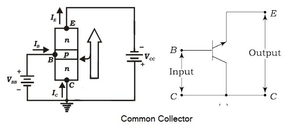
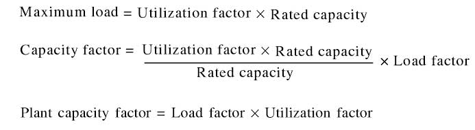
Ques 43. The plant capacity factor of a power plant may be calculated by the formula
- Sum of Individual max. demand ⁄ Max. demand of plant
- Average demand ⁄ Plant capacity✓
- Plant capacity ⁄ Average demand
- Station output ⁄ Plant hours of use
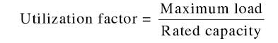
The plant capacity factor is the ratio of average demand to the maximum installed capacity of the station. Plant capacity factor = Average demand ⁄ Max. Plant capacity Capacity Factor The capacity factor indicates the extent of use of the generating station. It is different from the load factor because of the reason that the rated capacity of each plant is always greater than the expected maximum load due to some reserve capacity. Thus Utilization Factor It is defined as the ratio of maximum demand to the rated capacity of the plant Hence plant capacity factor is also the product of the load factor and the utilization factor.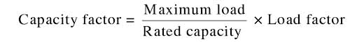
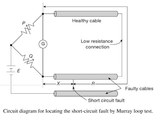
Ques 44. The test used to locate the high-resistance fault in a low resistance conductor circuit is
- Hopkinson’s test
- Murray Loop test✓
- Star/delta loop test
- Open-circuit test
Underground cables during their operation can experience various fault conditions. Whereas routine standard tests are there to identify and locate faults in high-voltage cables. special procedures, as will be described in this section are required for the localization of cable faults in low distribution voltage level cables. Determination of the exact location of fault sections in underground distribution cables is extremely important from the point of view of the quick restoration of service without loss of time for repair. The faults that are most likely to occur are ground faults where cable insulation may break down causing a current to flow from the core of the cable to the outer metal sheath or to the earth: or there may be short-circuited faults where an insulation failure between two cables, or between two cores of a multi-core cable results in the flow of current between them. Loop tests are popularly used in the localization of the aforesaid types of faults in low voltage cables. These tests can be carried out to localize a ground fault or a short-circuit fault, provided that an unfaulty cable runs along with the faulty cable. Such tests have the advantage that fault resistance does not affect the measurement sensitivity and that the fault resistance is not too high. Loop tests work on the simple principles of a Wheatstone bridge for the measurement of unknown resistances. There are several methods for locating the faults in underground cables. However, two popular methods known as loop tests are This method can be used for both low and high resistance faults in the following circumstances: The Murray loop test is the most common and accurate method of locating faults and should be made use of whenever circumstances permit. It can precisely locate the fault if the fault current is more than 1 mA, e.g. if the battery voltage is 100 volts, then the fault resistance may be of the order of 10 kΩ. The sensitivity depends on the detector used in the test circuit. A high gain electronic dc amplifier can be used for a higher degree of sensitivity of the instrument. In its simplest form, the faulty conductor is looped to a sound conductor of the same cross-sectional area and a slide wire or resistance box with two sets of Coils is connected across the open ends of the loop. A galvanometer is also joined across the open end of the loop and a battery or a dc had generator supplies the current for the test. Balance is obtained by adjusting the slide or resistance.
Murray Loop Test
Ques 45. DC current flowing through a conductor
- Concentrate towards the outer periphery
- Concentrate towards the center
- Distributed uniformly over the cross-section✓
- Distribute non-uniformly over the cross-section
When an ac current flows through a wire, a circulating magnetic field is created around it. Due to this, an emf is created in such a way so as to oppose this very reason. This emf is produced due to the inductance property of the wire. Since, inductive reactance, X = ωl, where ω is the angular frequency and l is the inductance, as frequency increases, X also increases. The flux is more at the center than at the surface of the conductor. Hence, the inductance at the center is much more than at the surface. The effective resistance, being inversely proportional to the square of the radius from the center, decreases as one goes from the center to the surface. Hence, the current flows in the low resistance path. Therefore, the current flow at the surface. This effect is also called as ‘skin effect’ and is much more pronounced at high frequencies. For direct current, ω =c0 because DC has no frequency. Therefore there is no inductive reactance of the conductor that has to be encountered by the flow of direct current in the ACSR conductor. Thus direct current can flow through the entire cross-section of the conductor while alternating current flows through the periphery.
Ques 46. The impedance of the circuit having V = 120 sin(314t) and current I = 12 sin(314 + π/6) is
- 20Ω
- 5Ω
- 10Ω✓
- 12Ω
Instantaneous Voltage V = 120sin(314t) Hence the Maximum value of Voltage Vm = 120 V Similarly, Instantaneous current I = 12 sin(314 + π/6) Hence the Maximum value of Current Im = 12 A Therefore Impedance Z = Vm/Im Z = 120 ⁄ 12 = 10Ω
Ques 47. When a long line operates at no load, the receiving end voltage is more than the sending end voltage. This is called as?
- Superposition effect
- Surge effect
- Skin effect
- Ferranti effect✓
A long transmission line has a large capacitance. When a long line is operating under the no-load condition, the receiving-end voltage is greater than the sending end voltage. This is known as the Ferranti effect. This phenomenon can be explained by the following reasoning. It was first noticed by Ferranti on overhead lines supplying a lightly loaded network. The Ferranti effect is due to the charging current of the line. The value of current at the sending end at no-load and normal operating voltage applied at the sending end is called the charging current. A simple explanation of the Ferranti effect can be given by approximating the distributed parameters of the line by lumped impedance as shown in Figure. Since usually, the capacitive reactance of the line is quite large as compared to the inductive reactance, under the no-load or lightly loaded condition, the line current is of leading pf. The phasor diagram is given below for this operating condition. The charging current produces a drop in the reactance of the line which is in phase opposition to the receiving-end voltage and hence the sending-end voltage becomes smaller than the receiving-end voltage. Note:-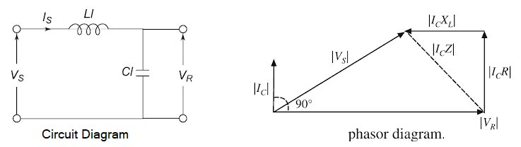
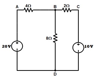
Ques 48. For the circuit given below, the current through 8Ω resistance will be.
- 1 A
- 1.42 A✓
- 4 A
- 2.5 A
Applying Nodal analysis at node B we get $\begin{array}{l}\dfrac{{V – 20}}{4} + \dfrac{V}{8} + \dfrac{{V – 10}}{2} = 0\\\\2V – 40 + V + 4V – 40 = 0\\\\V = 11.42\\\\{\text{Hence current through 8 ohm resistance is}}\\\\I = \dfrac{{V – 12}}{6}\end{array}$
Ques 49. A varistor is made up of
- Aluminium
- Carbon film
- Carborundum crystal✓
- Copper
A varistor is made up of carborundum crystal. A varistor is a voltage-dependent resistor used as a device to protect delicate electrical circuits from sudden, drastic changes in voltage. The variation in the resistance they offer to the flow of current under varying voltage is the basis of their use. Varistor materials offer high resistance at low voltages and low resistance at high voltages. A varistor is coupled with the main electrical circuit in an alternative pathway. Normally when the voltage in the circuit is low this device does not conduct any current because they offer high resistance to the flow of current and hence current flows through the main circuit. But as soon as a drastic increase in voltage occurs, its resistance falls off and it allows most of the current to pass through, thus protecting the main circuit from damage. Varistors are used in voltage stabilizers and for motor speed control. There are two types of varistors Silicon Carbide Varistor or Carborundum crystal Varistor:- These varistors are made from silicon carbide mixed with a suitable ceramic binder material. The mixture la prefixed to the desired shape and then wintered (compressed under heat) under controlled conditions to produce the hard ceramic body. Silicon-carbide varistors have a high power-handling capability and are used in high-voltage surge (lightning) arresters. The devices tend to draw considerable current in the normal state, and so they are commonly used in series with a gap that provides an open circuit until a surge occurs. This property makes silicon-carbide varistors unsatisfactory for low-voltage clamping operation. Newer zinc-oxide lightning arresters have better nonlinear characteristics and can be used without a gap. They are essentially crowbar devices but perform almost like clamping devices. Metal oxide Varistor:- They are made from the mixture of zinc oxide, bismuth oxide, and other powdered metals, which are pressed into the disc and then sintered above 1200°C At very low voltage they provide infinite resistance (open circa nit) and when the applied voltage exceeds rated voltage they appear as a short circuit and thus protect, the component they shunt. Metal-oxide varistors (MOVs), the most common clamping devices, are available for use at a wide range of voltages and currents. The range of parameters includes:
Ques 50. At a pressure of 500 V applied between each live conductor and earth for a period of one minute, the insulation resistance of low and medium voltage installation shall be at least:
- 1 kilo ohm
- 1 megaohm✓
- 0.5 kilo ohm
- 100 megaohm
One Meg ohm Rule for IR Value for Equipment Based upon equipment rating: < 1K V = 1 MΩ minimum As per IE Rules-1956 At a pressure of 1000 V applied between each live conductor and earth for a period of one minute the insulation resistance of HV installations shall be at least 1 Mega-ohm or as specified by the Bureau of Indian Standards. Medium and Low Voltage Installations- At a pressure of 500 V applied between each live conductor and earth for a period of one minute, the insulation resistance of medium and low voltage installations shall be at least 1 Mega ohm or as specified by the Bureau of Indian Standards] from time to time. At a pressure of 2.5 KV, DC applied between each live conductor and earth for a period of one minute, the insulation resistance of high voltage equipment shall be at least 5 MEGA-OHM or as specified in the relevant Indian Standard.
>1KV = 1 MΩ /1KV

