
Ques 51. When the fault current is 2000 A, for a relay setting of 50% with CT ratio 500/5, the plug setting multiplier will be
- 16
- 12
- 4
- 8✓
Plug setting multiplier of the relay is referred to as the ratio of the fault current in the relay to its pick up current. The current transformer ratio is 500 / 5. So, the CT can be provided a rated current of 5 Amps to the relay coil. Now the relay setting is 50%, then the relay can be operated for 5 × ( 50 / 100 ) = 2.5 Amps. This is the pick-up current of that relay. We know that the fault current is 2000 Amps. Hence, the fault current in the secondary of the CT is 5 × ( 2000 / 500) = 20 Amps. Therefore PSM of the relay is, PSM = 20 / 2.5 = 8 That means the fault current in the secondary of the CT is 8 times greater than the operating current of relay coil.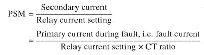
Ques 52. The resistivity of pure Germanium under the normal operating condition is
- 60Ω cm✓
- 1000Ω cm
- 600Ω cm
- 160Ω cm
Ques 53. While using clip-on type current transformer the primary is connected to ________ & secondary is connected to ________
- Ammeter; Feeder
- Ammeter; Voltmeter
- Voltmeter; Ammeter
- Feeder; Ammeter✓
Clip-on type transformer:
Ques 54. In an RLC series circuit the condition below the resonant frequency is:
- Xc > XL✓
- Xc + XL
- Xc < XL
- Xc = XL
REACTANCE Reactance is the property of resisting or impeding the flow of alternating current or voltage in inductors (coils) and capacitors. It is part of the total opposition to the flow o. AC, also expressed in ohms, is extra to resistance. There are two types of reactance: Inductive reactance is the opposition in an inductive circuit (with a coil). When the apply voltage to an inductor a magnetic field is created that slows the current down while the voltage is allowed to build up freely. The amount of back emf depends on the rate of change of the current, in that, the larger its frequency, the larger will be the reverse current, so the effect decreases with a decrease in frequency. Capacitive reactance exists in a capacitive circuit. and it decreases with an increase in frequency. Unlike inductive reactance, changes to the current occur before any changes to voltage-current now lead to the voltage because when you first apply a voltage, the current will be at its highest value, but the voltage will be at its lowest. Capacitive reactance is also measured in ohms and is inversely proportional to AC frequency, meaning that when the frequency is high reactance is low, and when it is low reactance is high. Capacitors, therefore, act as low resistance to high frequency and high resistance to low frequencies. Fig. shows phasor diagrams for series RLC circuit for three different keeping values of both L, and C constant. For any frequency f is lower than resonant frequency fo, inductive reactance is less than capacitive reactance. Hence the voltage drop VL is less than the voltage drop across the capacitor which is VC. So the current I leads the resultant supply voltage V and so the circuit behaves as a capacitive circuit at the frequencies which are less than fo. At f = fo, the inductive reactance equals capacitive reactance. Hence the voltage VLis equal to VC. The two voltages cancel each other and the resultant voltage is the same as the voltage VR. So the voltage and current are in phase. The circuit behaves as the pure resistive circuit at resonating frequency with a unity power factor. Similarly, for any frequency f higher than resonant frequency fo, capacitive reactance is very much less than inductive reactance. Hence the voltage drop VL is more than the voltage drop across the capacitor which is VC. So the current I lags the resultant supply voltage V and so the circuit behaves as an inductive circuit at the frequencies which are more than fo.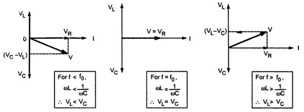
Ques 55. The effective value calculated for half-cycle of alternating current
- Same as calculated for one cycle✓
- Twice as calculated for one cycle
- Thrice as calculated for one cycle
- Half as calculated for one cycle
The effective or r.m.s. value of alternating current is that steady current (d.c.) which when flowing through a given resistance for a given time produces the same amount of heat as produced by the alternating current when flowing through the same resistance for the same time. It is also called the virtual value of a.c. and is represented by Irms or Ieff or Iv. For example, when we say that r.m.s. or effective value of an alternating current is 5A, it means that the alternating current will do work (or produce heat) at the same rate as 5A direct current under similar conditions. To determine r.m.s. value of a sinusoidal alternating current, we have to first square it, then take its mean over one cycle or half-cycle and then take the square root (note that r.m.s. value is calculated by making reverse operation, that is, the first square, then take mean and then take square root). Square of current i = Im sinθ = I2m sin2θ Its mean over one cycle is calculated by integrating it from 0 to 2π and dividing by the time period of 2π. Mean value of alternating current $\begin{array}{l}{\text{Mean of square}}\\\\ = 1/2\pi \int\limits_0^{2\pi } {{I^2}_m} {\sin ^2}\theta d\theta \\\\{\text{RMS Value}}\\\\{\rm{I = }}\sqrt {1/2\pi \int\limits_0^{2\pi } {{I^2}_m} {{\sin }^2}\theta d\theta } \\\\{\sin ^2}\theta = \dfrac{{1 – \cos 2\theta }}{2}\\\\{\rm{I = }}\sqrt {\dfrac{{{I^2}_m}}{{4\pi }}\int\limits_0^{2\pi } {(1 – \cos 2\theta } )d\theta } \\\\ = \sqrt {\frac{{{I^2}_m}}{{4\pi }}\left[ {\theta – \dfrac{{\sin 2\theta }}{2}} \right]_0^{2\pi }} \\\\ = \sqrt {\dfrac{{{I^2}_m}}{{4\pi }}} \times 2\pi \\\\ = \sqrt {\dfrac{{{I^2}_m}}{2}} \\\\I = \frac{{{I_m}}}{{\sqrt 2 }} = 0.707\end{array}$ If we calculate the r.m.s. value for half cycle, it can bc seen that we will get the same value by calculating as $\begin{array}{l}{\text{Mean of square}}\\\\ = 1/\pi \int\limits_0^\pi {{I^2}_m} {\sin ^2}\theta d\theta \\\\{\text{RMS Value}}\\\\{\rm{I = }}\sqrt {1/\pi \int\limits_0^\pi {{I^2}_m} {{\sin }^2}\theta d\theta } \\\\{\sin ^2}\theta = \dfrac{{1 – \cos 2\theta }}{2}\\\\{\rm{I = }}\sqrt {\frac{{{I^2}_m}}{{2\pi }}\int\limits_0^\pi {(1 – \cos 2\theta } )d\theta } \\\\ = \sqrt {\dfrac{{{I^2}_m}}{{2\pi }}\left[ {\theta – \dfrac{{\sin 2\theta }}{2}} \right]_0^\pi } \\\\ = \sqrt {\dfrac{{{I^2}_m}}{{2\pi }}} \times \pi \\\\ = \sqrt {\dfrac{{{I^2}_m}}{2}} \\\\I = \dfrac{{{I_m}}}{{\sqrt 2 }} = 0.707\end{array}$ Hence the r.m.s. value or effective value or virtual value of alternating current is 0.707 times the peak value of alternating current for the half-cycle as well as for the full cycle.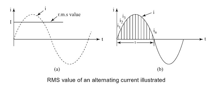
Ques 56. The frequency of EMF generated in India is
- 50 Hz✓
- 60 Hz
- 25 Hz
- 100 Hz
Almost the whole of the world uses a frequency of 50Hz and a voltage of 220-240(higher voltages for better efficiency in transmission). The exception, where 60Hz is used (with a voltage of 110-120), is the Americas (North and South) and the Caribbean (and parts of Japan and Korea). The reasons for India’s A.C (ALTERNATING CURRENT) frequency is maintained at 50Hz are very interesting. IT STARTS FROM THE BEGINNING OF ELECTRICITY- Early in the history of electricity, Thomas Edison’s General Electric company was distributing DC electricity at 110 volts in the United States. Then Nikola Tesla devised a system of three-phase AC electricity at 240 volts. Three-phase meant that three alternating currents slightly out of phase were combined in order to even out the great variations in voltage occurring in AC electricity. He had calculated that 60 cycles per second or 60Hz was the most effective frequency. Tesla later compromised to reduce the voltage to 120 volts for safety reasons. With the backing of the Westinghouse Company, Tesla’s AC system became the standard in the United States. Westinghouse chose 60 Hz because the arc light carbons(arc lamps) that were popular at that time worked better at 60 Hz than at 50 Hz. Europe goes to 50Hz and 230V Meanwhile, the German company AEG started generating electricity and became a virtual monopoly in Europe. Europe stayed at 120V AC until the 1950s, just after World War II. They then switched over to 220V for better efficiency in electrical transmission. Great Britain not only switched to 220V, but they also changed from 60Hz to 50Hz to follow the European lead. Since many people did not yet have electrical appliances in Europe after the war, the change-over was not that expensive for them. U.S stays at 120V, 60Hz The United States also considered converting to 220V for home use but felt it would be too costly, due to all the 120V electrical appliances people had. A compromise was made in the U.S. in that 240V would come into the house where it would be split to 120V to power most appliances. India got 50Hz because it was colonized by England, which when they developed their electrical systems, choose 50 Hz. From a technical point of view operating 50 Hz versus 60 Hz would not make much difference but, to achieve it, either the prime movers – for example, steam turbines, gas turbines, and diesel engines would need to be able to tolerate a 20% increase in speed or the alternators they drive – which produce the electricity would need to be completely rebuilt with extra poles and windings so that they could continue to run at the same rotational speed. We could have chosen any other frequency other than 50/60 Hz, but 50/60 HZ is an optimum frequency that keeps the transmission losses to tolerable limits.
They decided to use 50Hz instead of 60Hz to better fit their metric standards, but they stayed with 120V.
Certain household appliances such as the electric stove and electric clothes dryer would be powered at 240V.
Ques 57. In common emitter configuration the, the current amplification factor is
- β✓
- α
- Γ
- Δ
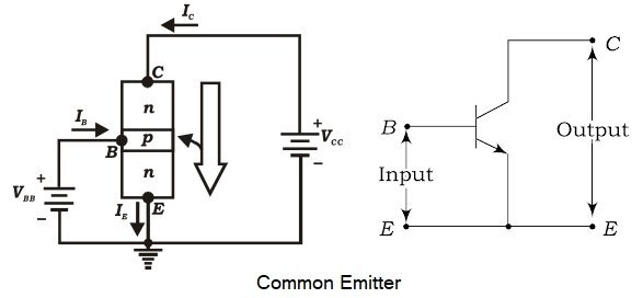
A Bipolar Junction Transistor (BJT) is a three-layer, two junction semiconductor device consisting of either two N-type and one P-type layer of material (NPN transistor) or two P-type and one N-type layer of material (PNP transistor). If a thin layer of N-type Silicon is sandwiched between two layers of P-type silicon. This transistor is referred to as PNP. Alternatively, in an NPN transistor, a layer of P-type material is sandwiched between two layers of N-type material. The term bipolar is to justify the fact that holes and electrons participate in the injection process into the oppositely polarised material. If only one carrier is employed (electron or hole). it is considered a unipolar device. CIRCUIT CONFIGURATION OF A BIPOLAR JUNCTION TRANSISTOR A transistor has three terminals: an emitter (E), base (B), and collector (C) and two junctions as emitter-base junction and collector-base junction. Each of these junctions requires two terminals for a biasing arrangement. When a transistor is connected to a circuit, it requires four terminals, i.e. two input terminals and two output terminals. Therefore, one of the three transistor terminals (emitter, base, and collector) is used as a common terminal between input and output. Depending upon the common terminal, the transistor may be connected to the three different configurations such as common emitter (CE), common base (CB), and common collector (CC) configurations. In the common-emitter configuration, the emitter of a transistor is connected to a common terminal between input and output as shown in Fig. The input signal is applied between the emitter and base terminals. The output will be obtained from the collector and emitter terminals. The common emitter configuration of the transistor is the most commonly used one in circuits. Common Emitter Current Gain β The current gain, beta (β), is defined for the common-emitter configuration of a BJT and can be defined in two forms: the dc current amplification factor (βdc) and the ac current amplification factor (βac). The dc current gain βdc is defined as the ratio of collector current to base current at a constant VCE under dc biasing conditions. ${\beta _{dc}} = \dfrac{{{I_C}}}{{{I_B}}}$ Similarly, the ac current gain, βacis defined as the ratio of change in collector current to a corresponding change in base current at a given VCE under ac signal conditions. Since the collector current is the output current for a common-emitter configuration and the base current is the input current. ${\beta _{ac}} = \dfrac{{{I_C}}}{{{I_B}}}$ A common-emitter configuration offers the following characteristics: Relation between α and β $\begin{array}{l}{I_E} = {I_B} + {I_c}\\\\\dfrac{{{I_c}}}{\alpha } = \dfrac{{{I_c}}}{\beta } + {I_c}\\\\{\text{Dividing both sides of the equation by }}{I_c}\\\\\dfrac{1}{\alpha } = \dfrac{1}{\beta } + 1\\\\{\text{On Solving}}\\\\\alpha = \dfrac{\beta }{{\beta + 1}}\\or\\\\\beta = \dfrac{\alpha }{{1 – \alpha }}\end{array}$ Note :- For common base configuration current amplification factor is α For common collector configuration, current amplification factor is Γ [ninja_tables id=27501]Common Emitter Configuration:
Ques 58. For a synchronous machine;
- Rotor speed < Stator field speed
- Rotor speed = Stator field speed
- Rotor speed = Stator field speed✓
- Rotor speed > Stator field speed
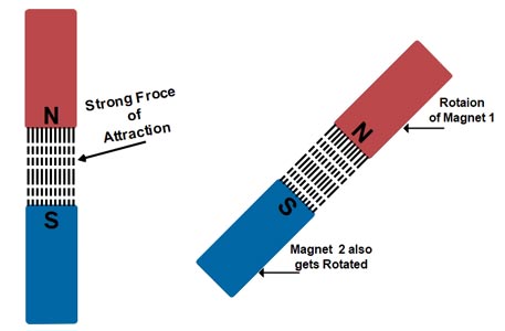
The synchronous motor is a truly constant speed motor. This is the specialty of this motor. Yet, it has very limited applications. To develop a steady torque, its rotor must be rotating at synchronous speed, Ns. This is the major defect of synchronous motors. Either it runs at synchronous speed, or it does not run at all. The stator field rotates at synchronous speed due to the three-phase currents supplied to its windings. In order to develop a continuous unidirectional torque, it is necessary that the stator and rotor poles do not move with respect to each other. This is possible only if the rotor also rotates at synchronous speed. Therefore Magnetic Locking between the poles is necessary to do so. The concept of Magnetic Locking For magnetic locking conditions, there must be two unlike poles and the magnetic axes of these two poles must be brought very nearer to each other. At zero speed or at any other speed lower than synchronous speed, the rotor poles rotate slower than the stator field. Therefore, in one cycle of rotation of the stator field, the N-pole of the rotor is for some time nearer to the N pole of the stator and for some other time nearer to the S-pole of the stator. As a result, the torque developed is for some time clockwise and for some other time anticlockwise. Consequently, the average torque developed remains zero. Hence the Synchronous Motor Run either on Synchronous Speed Or Not at all.
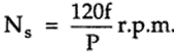 Where f = supply frequency
P = Number of poles

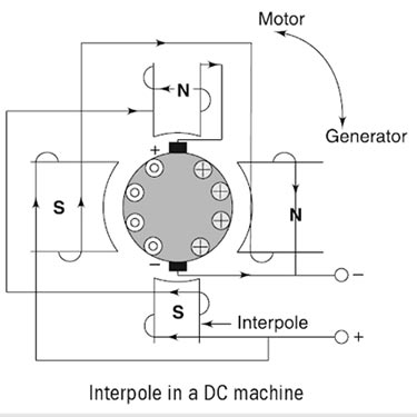
Ques 59. Direct current machines are connected to interpoles in order to
- Improve commutation under loaded condition✓
- Increasing the starting torque
- Decrease the windage loss
- Increase running torque
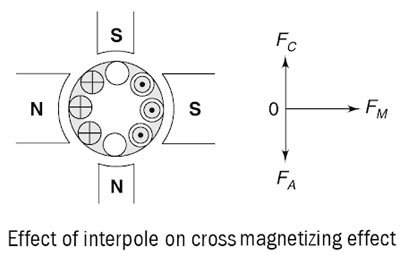
Interpoles In DC Machine Thus, we can conclude that: The mmf induced on the interpoles must be sufficient enough to neutralize the effect of armature reaction and to produce enough field in the interpole winding to overcome the reactance voltage due to commutation. Another important function of the interpole is to neutralize the cross-magnetizing effect of the armature reaction, as shown in Fig. Here, vector FM represents the MMF due to the main poles, FA represents the cross-magnetizing mmf due to the armature reaction and FC represents the interpole mmf which is directly opposite to the FA so that they cancel each other out. It is important to note here that the interpoles do not affect the flux distribution under the pole faces. So, even by using the interpoles in the machine, the flux weakening problem is not completely eliminated. Most medium-sized general-purpose motors correct the sparking problems with the interpoles and just live with the flux weakening problems. Main Functions of the Interpole
Ques 60. A consumer consumes 600 kWh per day at a load factor of 0.5. Without increasing the maximum demand, if the consumer increases the load factor to 0.8, the consumption of energy in kWh would be
- 480
- 960✓
- 300
- 900
Load factor = Average load x time / Maximum Demand x time 0.5 = 600 / Max. Demand in kW × 24 Max. Demand = 600 / 24 × 0.5 = 50 kW When load factor is increased by 0.8.then the energy consumed in 24 hrs Energy consumption = Load factor × max. demand × 24 = 0.8 × 50 × 24 = 960 kWh

