
Ques 61. In the common-base configuration, the current amplification factor is;
- β
- α✓
- Γ
- Δ
Common-Base Configuration: In this circuit configuration of a transistor, the base terminal is used as a common terminal between input and output as depicted in Fig. The input signal is applied between the emitter and base terminals. The output will be taken from the collection and base terminals. To explain the operation of NPN and PNP transistors, the common base configuration is used. Common-Base dc Current Gain The common-base dc current gain (α) is defined as the ratio of the collector current, Ic, and the emitter current IE and it is represented by α. The dc current gain α can be expressed as $\alpha = \dfrac{{{I_C}}}{{{I_E}}}$ Since the collector current is always less than the emitter current, the dc current gain α is always less than unity. Usually, the value of α is about 0.98. The dc current can be made closer to unity by controlling the width and doping level of base region as less as possible. Practically, α varies between 0.95 to 0.998. From the above equation, we get the collector current IC = αIE. The emitter current is IE = IB + IC as IC = αIE IB = (1 – α)IE A common-base configuration offers the following characteristics: Note:- For common emitter configuration current amplification factor is β For common collector configuration, the current amplification factor is Γ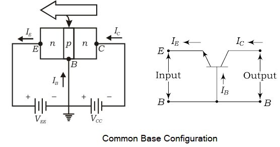
IE = IB + αIC
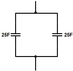
Ques 62. The equivalent capacitance of the combination given below is
- 12.5 F
- 25 F
- 50 F✓
- 100 F
Since the two capacitor are connected in the parallel combination therefore there equivalent capacitance is Ceqv = C1 + C2 = 25 + 25 Ceqv = 50 F
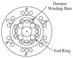
Ques 63. Damper winding in synchronous motors is used to
- Suppress hunting✔
- Improve power factor
- Develop reluctance torque
- Improve the efficiency
HUNTING If the torque output of a prime mover pulsates, it may cause the rotor of the alternator to be pulled ahead of, and then behind, its normal running position. A diesel engine is one example of a prime mover that has a pulsating torque output. If an alternator is used with a diesel engine, the alternator rotor periodically will move slightly faster and then slower. This pulsating or oscillating effect is called hunting. It causes the current to surge back and forth between alternators operating in parallel. This condition is unsatisfactory and may become cumulative, resulting in such a large increase in the current between the alternators that the overload relays open the circuit. Hunting can be corrected by the use of a heavy flywheel. A damper winding is often used in the rotating field structure to minimize the pulsating torque. Figure. showed a damper winding, which is often called an amortisseur winding. This winding is embedded in slots in each of the pole faces of the rotating field. The armortisseur winding consists of heavy conductors that are brazed or welded to two end rings. At the instant that hunting develops, the path of the armature flux changes so that it cuts the short-circuited conductors of the amortissuer winding. This change in the flux path produces induced currents in the damper winding. The currents oppose the force-producing them (by Lenz’s law). The proper design of the damper winding ensures that the effects of hunting are canceled by the induced currents in the short-circuited conductors. Note:- The AVR(Automatic voltage regulator) consists basically of a circuit fed from the alternator output voltage which detects small changes in voltage and feeds a signal to an amplifier which changes the excitation to correct the voltage. Stabilizing features are also incorporated in the circuits to avoid ‘hunting’ (constant voltage fluctuations) or overcorrecting.
Ques 64. The frequency of instantaneous power in a purely capacitive circuit is
- Double the frequency of applied voltage✓
- Independent of the frequency of applied votlage
- Half of the frequency of applied voltage
- Same as the frequency of applied voltage
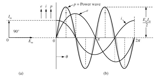
Consider a pure capacitive circuit connected to an AC supply. When a pure capacitor is connected to AC source, a changing value of the applied voltage causes the capacitor to charge and discharge alternatively. The charge that flows through the capacitor is proportional to the capacitance (size of the capacitor) and the applied voltage across the capacitor. Power in the Purely capacitive circuit In the case of the pure capacitive circuit, the current leads the applied voltage by 90° Let the voltage V = Vm sinωt is applied to a pure capacitive circuit. Then the resulting current will be I = Im sin(ωt + π/2) The power curve can be derived by multiplying the instantaneous values of the applied voltage by instantaneous currents. P = VI = Vm sinωt × Im sin(ωt + π/2) i.e P = Vm Im sinωt sin(ωt + π/2) However sin(ωt + π/2) = cosωt ∴ P = Vm Im sinωt cosωt or P = ½ Vm Im (2sinωt cosωt) ∴ P = ½ Vm Imsin2ωt or P = Vm sinωt × Im sin(ωt + φ) P = VmIm sinωt . sin(ωt + φ) Multiplying and dividing the above equation by 2 we get and as we know that $\begin{array}{l}P = \dfrac{{{V_m}{{\mathop{\rm I}\nolimits} _m}}}{2}2\sin \omega t.\sin (\omega t + \Phi )\\\\ = \dfrac{{{V_m}{{\mathop{\rm I}\nolimits} _m}}}{2}\left[ {\cos (\omega t – \omega t – \Phi ) – \cos (\omega t + \omega t + \Phi )} \right]\\\\ = \dfrac{{{V_m}{{\mathop{\rm I}\nolimits} _m}}}{2}\left[ {\cos \Phi – \cos (2\omega t + \Phi )} \right]\end{array}$ Clearly, the instantaneous power P is composed of two terms. During the first quarter cycle, the power curve is above the horizontal axis and is positive (0 to 90). The circuit draws energy from the source and the capacitor is charged. The energy is stored in the electric field of the capacitor. During the second quarter cycle, the power curve is below the horizontal and is negative (90 to 180). The capacitor is discharged and the energy from the dielectric field is returned to the source. The energy stored in the electric field during the first quarter cycle is equal to the energy returned to the source during the second quarter cycle in a purely capacitive circuit. Therefore the total active energy during each cycle of the current is zero. The active power over the complete cycle of current in a purely capacitive circuit is zero. Note:- Whether is a pure resistive circuit or a pure capacitive circuit the frequency of instantaneous power is always double the frequency of the applied voltage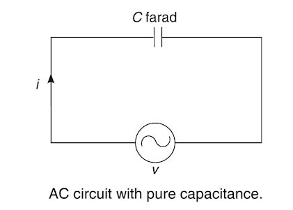
2sinA.sinB = cos(A − B) − cos(A + B)
Ques 65. At a pressure of 1000 V applied between each live conductor and earth for a period of one minute, the insulation resistance of low and medium voltage installation shall be at least:
- 1 kilo ohm
- 1 megaohm✓
- 0.5 kilo ohm
- 100 megaohm
One Meg ohm Rule for IR Value for Equipment Based upon equipment rating: < 1K V = 1 MΩ minimum As per IE Rules-1956 At a pressure of 1000 V applied between each live conductor and earth for a period of one minute the insulation resistance of HV installations shall be at least 1 Mega-ohm or as specified by the Bureau of Indian Standards. Medium and Low Voltage Installations- At a pressure of 500 V applied between each live conductor and earth for a period of one minute, the insulation resistance of medium and low voltage installations shall be at least 1 Mega ohm or as specified by the Bureau of Indian Standards] from time to time. At a pressure of 2.5 kV, DC applied between each live conductor and earth for a period of one minute, the insulation resistance of high voltage equipment shall be at least 5 MEGA-OHM or as specified in the relevant Indian Standard.
>1KV = 1 MΩ /1KV
Ques 66. The effective voltage of an alternating voltage is
- Instantaneous Voltage
- Maximum voltage
- RMS voltage✓
- Average
The effective or r.m.s. value of alternating current is that steady current (d.c.) which when flowing through a given resistance for a given time produces the same amount of heat as produced by the alternating current when flowing through the same resistance for the same time. It is also called the virtual value of a.c. and is represented by Irms or Ieff or Iv. An instantaneous voltage is the value of an AC voltage at a particular instant. For example, the maximum voltage shown in Figure is an instantaneous voltage; the positive maximum voltage occurs at 90°, and the negative maximum voltage occurs at 270°. Electricians generally consider that the most important instantaneous AC voltages are the maximum (crest or peak) voltage and the effective voltage. Let us try to explain what is meant by the effective voltage and then observe why it is so important. The effective voltage is 70.7 percent of the peak voltage and occurs at 45°. Practically all AC voltmeters read the effective value of an AC voltage. The effective value is also called the root-mean-square -(RMS) value because it is the square root of the average of the squared values between zero and maximum. The effective value of an AC current is stated in terms of an equivalent DC current. The phenomenon used for standard comparisons is the heating effect of the current. Since nearly all AC voltmeters indicate effective values, this particular value is always understood when an electrician speaks of 120 volts, 240 volts, etc. The word effective is understood, although it is not commonly stated in electrical diagrams and instruction sheets. If an electrician wishes to speak of a crest or peak voltage, he will state “169 crest volts” or “169 peak volts,” for example. An effective voltage of 120 volts has a crest voltage of approximately 169 volts.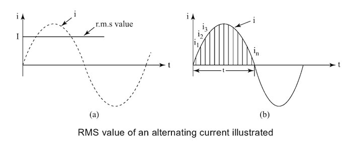
Ques 67. In case of a DC machine the value of load current at maximum efficiency is
$\begin{array}{l}1.{I_L} = \sqrt {\dfrac{{{\text{Variable losses + Constant Losses}}}}{{{\text{Armature Resistance}}}}} \\\\2.{I_L} = \sqrt {\dfrac{{{\text{Constant Losses}}}}{{{\text{Armature Resistance}}}}} \\\\3.{I_L} = \sqrt {\dfrac{{{\text{Constant Losses}}}}{{{{\rm{R}}_a} + {R_f}}}} \\\\4.{I_L} = \sqrt {\dfrac{{{\text{Variable losses}}}}{{{\text{Armature Resistance}}}}} \end{array}$.
In a DC machine, the condition of maximum efficiency occurs when the variable losses (copper Losses Pc) is equal to the constant loss (Iron Losses I2LRa) (since iron loss occurs in the armature of a DC machine because the armature core is made of iron and it rotates in a magnetic field. Hence from the above discussion, it is clear that I2LRa = Pc $\begin{array}{l}{I^2}_L = \dfrac{{{P_c}}}{{{R_a}}}\\\\{I_L} = \sqrt {\frac{{{P_c}}}{{{R_a}}}} \\i.e\\{I_L} = \sqrt {\dfrac{{{\rm{Variable losses}}}}{{{\text{Armature Resistance}}}}} \end{array}$
Ques 68. The effect of unequal EMF in the parallel paths of lap wound armature winding of a DC machine may be neutralized by
- Inter-poles
- Graphite Brushes
- Commutator
- Equalizer connection✓
In simplex lap winding, the number of parallel paths is equal to the number of poles and all the conductors of anyone parallel path lie under one pair of poles. If the flux produced by all the poles is exactly the same, the emf induced in each parallel path and hence the current carried by each one of them will be equal. But in spite of best efforts, this condition cannot be obtained due to different properties of the steel used for the construction of poles and variation of air gap between the poles and armature. Hence, there is always a slight difference in the induced emf in various parallel paths which results in large circulating currents in the armature winding. The various reason of circulating current in a Lap wound DC machine are This circulating current causes a continuous I2R loss in the winding and tends to heat the armature. It may also cause an undue amount of sparking a the brushes (since the current circulates from one path to another through brushes) and may lead to overloading of the brushes and conductors in the armature. Circulating current also introduces commutation difficulty in a dc machine. Due to heavy sparking at the brushes which not only heats up the machine but also causes undue burning and wear of commutator and brushes. If it is carried too far, it may result in a flashover from positive to negative brushes. To overcome this detrimental effect, usually, equalizing connections are provided in all lap-wound armatures. These connections are made with the help of very low resistance (almost zero) wires called equalizers. An equalizer is a copper wire having very low resistance and is used to connect the points of different parallel paths of armature winding which should have the same potential under ideal conditions. These equalizer rings carry the circulating current and relieve the brushes to carry this circulating current. Under this condition, the brushes are to carry only the load current. The desired arrangement is to connect every coil of the armature to an equalizer. But it is not possible in practical, as the number of such connections would be very large. It is sufficient to connect every third or fourth coil, and usually, 10 to 20 equalizer rings are used. The functions of the equalizer rings are For making equalizer connections, the number of coils is should be multiple of the number of poles and at the same time, the number of coils per pole should be divisible by a small number 2, 3 or 4. Number of equalizer rings = Number of coils- sides Per Pole ⁄ 2 The number of connections to one equalizer rings = Number of pairs of poles
Ques 69. The material used for the construction of the control rod in a nuclear reactor is
- Silicon
- Cadmium✓
- Copper
- Graphite
Control rods are used in nuclear reactors to control the fission rate of uranium and plutonium. During the fission of U-235 nuclei, for every one slow neutron absorbed, three fast-moving neutrons are produced. Assuming that these three neutrons are slowed down, they will produce an uncontrolled nuclear fission reaction as their number will multiply exponentially. This will cause a nuclear explosion. In order to sustain the nuclear reaction in a controlled manner only one neutron per fission reaction is needed. Thus, the excess neutrons must be absorbed by suitable materials. Boron and cadmium are suitable materials for capturing excess neutrons and are called absorbers The absorbers are used in the form of rods o rectangular strips and are commonly called controlling rods. When control rods are fully inserted into fuel within the reactor, they absorb all the neutrons. This in turn completely stops chain reaction and hence nuclear fire dies. This particular position of controlling rods is called the shut down position of the nuclear reactor. During actual operation, the controlling rods are slowly taken out from the nuclear fuel within the reactor, till they absorb the right amount of neutrons and leave only as many neutrons which are just necessary to sustain controlled nuclear fission. When this stage is reached, the reactor is said to have gone critical.
Ques 70. In a 3 phase alternator, the rotating part is
- Field system✓
- Commutator
- Armature system
- Slip ring
FIELD AND ARMATURE CONFIGURATIONS There are two arrangements of fields and armatures: In large alternators, the rotating field arrangement is usually forward due to the following advantages. Hence in almost all of the alternators, the armature is housed in the stator while the dc field system is placed in the rotor.
ADVANTAGES OF ROTATING FIELD IN AN ALTERNATOR
Ques 71. The pair of donor impurities for the semiconductor material is
- Arsenic and Antimony✓
- Arsenic and Argon
- Gallium and Helium
- Gallium and Indium
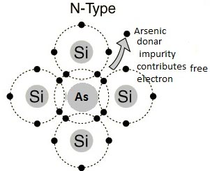
Extrinsic Semiconductor In order to change the properties of intrinsic semiconductors a small amount of some other material is added to it. The process of adding other material to the crystal of intrinsic semiconductors to improve its conductivity is called doping. The impurity added is called dopant. The doped semiconductor material is called extrinsic semiconductors. The doping increases the conductivity of the basic intrinsic semiconductors hence the extrinsic semiconductors are used in practice for the manufacturing of various electronic devices such as diodes, transistors etc. Depending upon the type of impurities, the two types of extrinsic semiconductors are, N-TYPE Impurity The impurity material having five valence electrons is called the pentavalent atom. When this is added to an intrinsic semiconductor, it is called donor doping as each impurity atom donates one free electron to an intrinsic material. Such an impurity is called donor impurity. Examples of such impurities are arsenic, bismuth, phosphorous, Antimony, etc. This crests an extrinsic semiconductor with a large number of free electrons called an n-type semiconductor. Germanium and Silicon are tetravalent. The impurity atoms may be either pentavalent or trivalent, i.e., for groups V and III of the periodic table. If a small quantity of a pentavalent impurity (having 5-electrons in tt outermost orbit) like Arsenic (As), Antimony (Sb), or Phosphorus (P) is introduced in Germanium, it replaces the equal number of Germanium atoms without changing the physical state of the crystal. Each of the four out of five valency electrons of impurity says Arsenic enters into covalent bonds with Germanium, while the fifth valence electron is set free to moo from one atom to the other as shown in Fig. The impurity is called donor impurity as it donates an electron and the crystal is called an N-type semiconductor. A small amount of Arsenic (impurity) injects billions of free electrons into Germanium thus it creasing its conductivity enormously. In an N-type semiconductor, the majority carriers of charge are the electrons and holes as minority carriers. This is because when donor atoms are added to a semiconductor, the extra free electrons give the semiconductor a greater number of free electrons than it would normally have.
Ques 72. The data tabulated of the power system is as follow
Line voltage = 11 kV
Generated power = 558 kW
Load Power = 443 kW
Load current = 50 A
Then the resistance of the power line connected to it is:
- 46Ω✓
- 40Ω
- 220Ω
- 50Ω
The generated power in an electrical system is the sum of the load power and power losses(Mainly losses of transmission line and transformer) PG = PD + PL Now the given generated power PG = 558 and the given load Power PD = 443 therefore PL = PG − PD = 558 − 443 PL = 115000 W Power Loss = I2R R = PL ⁄ I2 R = 115000 ⁄ 502 R = 46Ω
Ques 73. What will be the speed of the Prime mover of an alternator having 2 poles and 50 Hz?
- 3000 RPM✓
- 1500 RPM
- 1000 RPM
- 500 RPM
The synchronous speed of an alternator is given as Ns = 120f/P Ns = 3000 RPM
= 120 × 50/2
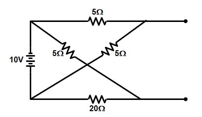
Ques 74.The current supplied by the battery through AB terminal is
- 1.4 A✓
- 3 A
- 0.43 A
- 0.4 A
The above circuit is a simple series parallel connection The series resistance 5Ω and 5Ω are in parallel with the series resistance 20Ω and 5Ω Now resistance 10Ω and 25Ω are in parallel therefore equivalent resistance become Reqv = (25 × 10) ⁄ (25 + 10) Reqv = 50 ⁄ 7 Hence current supplied by the battery through AB terminal is I = V ⁄ Reqv = 10 × 7 ⁄ 50 = 1.4 A I = 1.4 A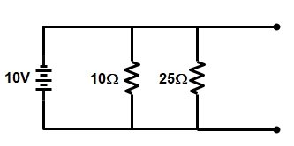
Ques 75. During charging the capacitor C = 100μF through a resistance of 1 KΩ applied with 100 V, the voltage of time constant is
- 63.7 V
- 36.7 V
- 63.2 V✓
- 100 V
An RC time constant tells us about the relation between time, resistance, and capacitance. The time taken by the capacitor is directly proportional to the amount of resistance and capacitance in the circuit. The time constant reflects the time required for the capacitor to charge up to 63.2% of the applied voltage. So 63.2% of 100 V = 63.2 Volt
DMRC 2017 Solved Paper CLICK HERE
For NMRC 2017 Solved Paper CLICK HERE
DMRC 2016 Solved Paper CLICK HERE
For DMRC 2015 Solved Paper CLICK HERE
For DMRC 2014 Solved Paper CLICK HERE
For SSC JE CONVENTIONAL Paper 2017 CLICK HERE
For SSC JE CONVENTIONAL Paper 2016 CLICK HERE

