
Ques 21. Select the motor with the least starting torque
- Capacitor-start induction-run motor
- Capacitor-start capacitor- run motor
- R-split phase induction motor
- Shaded Pole motor✓
Shaded-pole motor has a salient pole staler similar to the stator of a dc machine. The pole is laminated to reduce the core losses. The pole is physically divided into two sections as shown in fig. A heavy, short-circuited copper ring, called the shading coil, placed on the smaller section of the pole. This section covers around one-third of the pole arc and is called the shaded portion of the pole. The remaining two-thirds section of the pole is referred to as the unshaded portion. The main single-phase winding is wound on the entire pole section. The rotor used is similar to the rotor of any other single-phase induction motor. When a single-phase supply is fed to the main winding, an alternating flux is produced in the pole. A portion of this flux links with the shading coil and induces a voltage in it. As a shading coil is a short-circuited coil, a large current flows in it. The current in the shading band causes the flux in the shaded portion of the pole to lag the flux in the unshaded portion of the pole. Thus the flux in the shaded portion reaches its maximum value after the flux in the unshaded portion reaches its maximum. This is equivalent to a progressive shift of the flux from the unshaded to the shaded portion of the pole, that is it is similar to a rotating field moving from the unshaded to the shaded portion of the Pole. Hence. the motor reproduces a starting torque. Because of the small phase of displacement of the currents in the mail and the auxiliary winding and because of the winding misalignment lower than π/2 the start torque is very low. Therefore shaded-pole motors are especially suited for small fans and pumps. Other applications are juice presses, clothe dryers, grills, simple butterfly control waves, massage apparatus, hot-air stoves, and cabinet fans. Drives for reversing duties can be built with two motors assembled homologously. Shaded-pole motors are low-cost motors. Because of their low efficiency, they mostly need intensive cooling.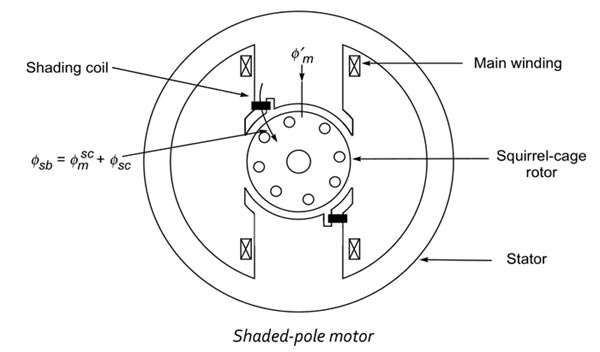
Ques 22. The schematic arrangement given is of protection of alternator against
- Earth fault
- Turn to turn fault in any single stator winding
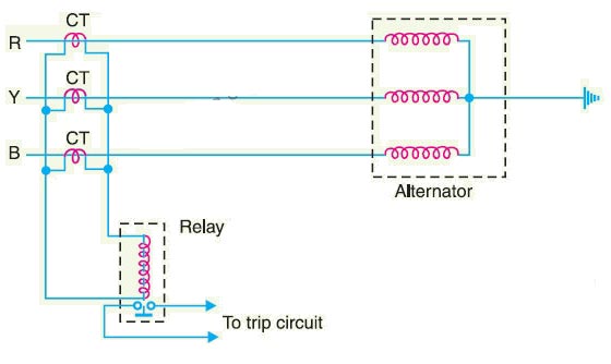
- Unbalance Loading✓
- Insulation failure of the stator winding
Unbalanced loading is not a direct fault, does not apply any harm but the cause of unbalanced is harmful like the grounding of one phase, or short circuit of phase to phase. Unbalanced loading means the circulation of the different phase current ratios in three phases of an alternator. In normal conditions, the difference in phase current varies +/- 5 %, but when this difference exceeds then it becomes an unbalanced condition. The reasons for the unbalanced load conditions are, To sense and protect the unbalanced loading a simple conception is used to compare the value of two currents i.e Incoming current and the Outgoing current of the stator coil. In normal conditions, the value of two currents will be equal, during fault conditions there will be some difference, if the value is not in the tolerable range then this circuit can send a trip signal. As shown in the above circuit the secondaries of three CTs are shorted, so the sum of normal phase currents is zero, with no current in the trip coil. In some instances if there is some unbalanced, then there will be some current in the secondary, which will eventually send a trip signal. The unbalanced loading of the generator results in the circulation of negative sequence currents. These currents produce a rotating magnetic field. This rotating magnetic field rotates at a synchronous speed with respect to the rotor. The direction of rotation of this magnetic field is opposite to that of the rotor. Hence effectively the relative speed between the two is double the synchronous speed. Thus the e.m.f. gets induced, having double the normal frequency in the rotor winding. The circulating currents due to the induced e.m.f. are responsible to overheat the rotor winding as well as rotor stampings. A continuous unbalanced load of more than 10% of the rated load causes tremendous heating which is dominant in the case of the cylindrical rotor of turbo-alternators.
Ques 23. Solid state power supplies are protected from high surge voltage due to lightning using:
- Zinc-oxide-Based Varistor
- Cermet Resistor
- Metal Glaze resistor
- Silicon carbide resistor✓
Silicon Carbide Varistor or Carborundum crystal Varistor:- These varistors are made from silicon carbide mixed with a suitable ceramic binder material. The mixture la prefixed to the desired shape and then wintered (compressed under heat) under controlled conditions to produce the hard ceramic body. Silicon-carbide varistors have a high power-handling capability and are used in high-voltage surge (lightning) arresters. The devices tend to draw considerable current in the normal state, and so they are commonly used in series with a gap that provides an open circuit until a surge occurs. This property makes silicon-carbide varistors unsatisfactory for low-voltage clamping operation. Newer zinc-oxide lightning arresters have better nonlinear characteristics and can be used without a gap. They are essentially crowbar devices but perform almost like clamping devices. A cermet is a composite material composed of ceramic and metal materials. A cermet is ideally designed to have the optimal properties of both a ceramic, such as high-temperature resistance and hardness, and those of a metal, such as the ability to undergo plastic deformation. The cermet resistor can be obtained by depositing highly stable metallic solutions (like silver/gold with palladium or chromium with silicon monoxide or oxides of rhodium/zirconium) in an organic solvent on the ceramic substrate. This is done by micro screen printing, roller printing, or dipped proceed. When the substrate la heated (1000°C), the organic particles evaporate and the metal fuses into the ceramic substrate. Advantaged Cermet resistors are offering the following advantages. The metal glaze resistor is also a fixed resistor, similar to the metal film resistor. This resistor is made by combining metal with glass. The compound is then applied to a ceramic base as a thick film. The resistance is determined by the amount of metal used in the compound. Tolerance ratings of 2% and 1% are common. For most materials, a very high sheet resistance can only be obtained by using an extremely thin film. By using a composite material such as a metal glaze, a thick and therefore more stable high ohmic film can be made. Such a film is produced by dipping the ceramic rod in a paste and drying and firing the layer. As cylindrical resistors, cermet or metal glaze resistors are mostly used for high-resistance values and high voltages. The available resistance range is 100 kΩ to 100 MΩ. The stability is good and the current noise is acceptable for such high values. The resistance of the metal glaze resistor depends on the amount of metal and glass added
Cerment Resistor
Cermet or Metal Glaze Resistors
Metal glaze film with a higher amount of metal particles and a lower amount of glass provides low resistance to the electric current. Hence, a large amount of electric current flows through the metal glaze resistor.
Ques 24. Two identical coils X and Y of 500 turns each lie in parallel planes such that 80% of flux produced by one coil links with the other. If a current of 5 A flowing in X produces a flux of 10 mWb in it, find the mutual inductance between X and Y
- 0.8 H✓
- 8 H
- 0.16 H
- 16 H
Coefficient of Magnetic Coupling During Mutual Inductance between two coils, we assume that the flux produced by one coil is entirely linked with the other coil. But practically it is not true, the certain portion of the flux of one coil does not link with the other coil. The ratio of the portion of the flux of one coil linked with the other coil to the entire flux produced by the coil is referred to as the coefficient of magnetic coupling. Consider two coils having self-inductance L1 and L2 placed very close to each other. Let the number of turns of the two coils be N1 and N2 respectively. Let coil-1 carry current I1 and coil- 2 carry current i2. Due to current i1, the flux produced is Φ1 which links with both the coils. Then the mutual inductance between two coils can be written as $M = \dfrac{{{N_1}{\Phi _{21}}}}{{{I_1}}}$ Where Φ21 is the part of the flux Φ1 linking with the coil 2. Now as per given question Number of turns N1 = 500 Current I = 5A Flux Produced in X Φ1 = 10 mWb = 1 × 10⁻² Wb Fluxed Linked with Y Φ21 = 1 × 10-2 × 0.8 = 0.8 × 10⁻² Wb $\begin{array}{l}M = \dfrac{{500 \times 0.8 \times {{10}^{^{ – 2}}}}}{5}\\\\M = 0.8H\end{array}$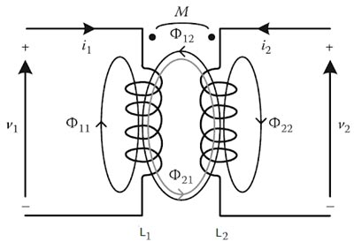
Ques 25. In a transformer, the load current on primary may be calculated as
$\begin{array}{l}1.{I_1} = \left( {\dfrac{{{V_1}}}{{{V_2}}}} \right) \times {I_2}\\\\2.{I_1} = \left( {\dfrac{{{N_1}}}{{{N_2}}}} \right) \times {I_2}\\\\3.{I_1} = \left( {\dfrac{{{I_2}}}{{{I_1}}}} \right) \times {I_2}\\\\4.{I_1} = \left( {\dfrac{{{N_2}}}{{{N_1}}}} \right) \times {I_2}\end{array}$
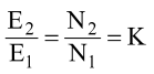
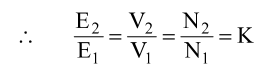
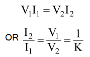
Voltage Transformation Ratio (K) The constant K is called as Voltage transformation ratio and it is given as: For an ideal transformer, there is no voltage drop in the windings, therefore, E1 = E2and V1 = V2. If N2 > N1 and K >1 then the transformer is called a step-up transformer. There are no losses in an ideal transformer therefore volt-ampere input of the primary will be always equal to the volt-ampere of the secondary. $\begin{array}{l}\dfrac{{{I_2}}}{{{I_1}}} = \dfrac{{{N_1}}}{{{N_2}}} = \dfrac{{{V_1}}}{{{V_2}}}\\\\Hence\\\\{I_1} = \left( {\dfrac{{{N_2}}}{{{N_1}}}} \right) \times {I_2}\end{array}$ From the above equation, it is clear that current is inversely proportional to the voltage i.e if we will increase the value of voltage then the value of current will decrease.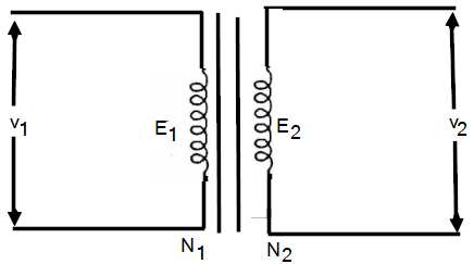
If N1 > N2 and K< 2 then the transformer is called a step-down transformer.
Ques 26. When a DC series motor is started with an open field winding connection, the motor will
- Run normally and deliver more output
- Run normally but deliver less output
- Have a dangerously high speed
- Not start✓
At the normal operating conditions of the DC series motor. The field winding is connected in series with the armature winding. This means that power will be applied to one end of the series field winding and to one end of the armature winding (connected at the brush). When the voltage is applied, the current begins to flow from negative power supply terminals through the series winding and armature winding. Now if the field winding of the DC series motor gets open then we have cut the supply off the motor as the field is in series with the armature. Hence the current will stop flowing in the entire circuit and the motor will not start at all.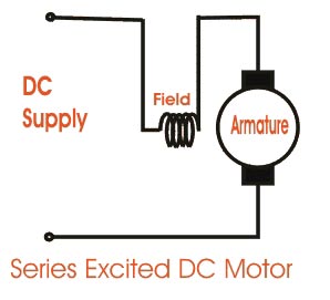
Ques 27. What is the principle behind the working of phase sequence indicators of 3-φ unbalanced 3-wire load?
- Phase current depends on the phase sequence
- Line current depends on the phase sequence
- Line voltage depends on the phase sequence
- Phase Voltage depends on the phase sequence✓
Any polyphase load in which the impedances in one or more phases differ from the impedance of other phases is said to be an unbalanced load.
The order in which the individual phase voltages attain their respective maximum values in a three-phase system is called phase sequence. So whether it is a balanced system or an unbalanced system the phase voltage depends on the phase sequence.
Conventionally the three phases are designated as red-R, yellow-Y, and blue-B phases.
The phase sequence is said to be RYB if R attains its peak or maximum value first with respect to the reference as shown in the counterclockwise direction followed by Y phase 120° later and B phase 240° later than the R phase.
The phase sequence is said to be RBY if R is followed by B phase120° later and Y phase 240° later than the R phase. By convention, RYB is considered positive while the sequence RBY is negative.

Then Red phase VRN = Vm sinθ
Yellow Phase VYN = Vm sin(θ – 120°)
Blue Phase VBN = Vm sin(θ – 240°)
or VBN = Vm sin (θ + 240°)
The effects of phase sequence of the source voltages are not of considerable importance for applications like lighting, heating, etc. but in the case of a three-phase induction motor, reversal of sequence results in the reversal of its direction.
In the case of an unbalanced polyphase system, a reversal of the voltage phase sequence will, in general, cause certain branch currents to change in magnitude as well as in phase position. Even though the system is balanced, the readings of the two wattmeters in the two wattmeter method of measuring power interchange when subjected to a reversal of phase sequence when two or more three-phase generators are running parallel to supply a common load, reversing the phase sequence of any one machine causes severe damage to the entire system.
Ques 28. In the common collector configuration of bipolar junction transistor (BJT), the output voltage is
- Shifted by 270° from the input voltage
- In phase with the input voltage✓
- Out of phase with the input voltage
- Shifted by 90° from the input voltage
A Bipolar Junction Transistor (BJT) is a three-layer, two junction semiconductor device consisting of either two N-type and one P-type layer of material (NPN transistor) or two P-type and one N-type layer of material (PNP transistor). If a thin layer of N-type Silicon is sandwiched between two layers of P-type silicon. This transistor is referred to as PNP. Alternatively, in an NPN transistor, a layer of P-type material is sandwiched between two layers of N-type material. In the common collector configuration of bipolar junction transistor (BJT), the output voltage is in phase with the input voltage. The term bipolar is to justify the fact that holes and electrons participate in the injection process into the oppositely polarised material. If only one carrier is employed (electron or hole). it is considered a unipolar device. CIRCUIT CONFIGURATION OF A BIPOLAR JUNCTION TRANSISTOR A transistor has three terminals: an emitter (E), base (B), and collector (C) and two junctions as emitter-base junction and collector-base junction. Each of these junctions requires two terminals for a biasing arrangement. When a transistor is connected to a circuit, it requires four terminals, i.e. two input terminals and two output terminals. Therefore, one of the three transistor terminals (emitter, base, and collector) is used as a common terminal between input and output. Depending upon the common terminal, the transistor may be connected to the three different configurations such as common emitter (CE), common base (CB), and common collector (CC) configurations. Common-Collector Configuration In a common-collector configuration, the collector terminal of a transistor is connected as a common terminal between input and output as shown in fig. The base and collector terminals are used to apply the input signal whereas the output signal is obtained from the emitter and collector terminal. The CC configuration is also commonly known as the emitter follower or the voltage follower. This is because the output signal across the emitter is almost the replica of the input signal with little loss. Since the emitter is the output terminal, it can be noted that the output voltage from a common collector circuit is the same as its input voltage. Hence the phase shift between the input voltage and the output voltage is 0°. In other words, the output voltage follows the input voltage and hence the voltage gain will be a maximum of one. The common-collector configuration is used primarily for impedance-matching purposes since it has a high input impedance and low output impedance, opposite to that of the common-base and common-emitter configuration. Note:- 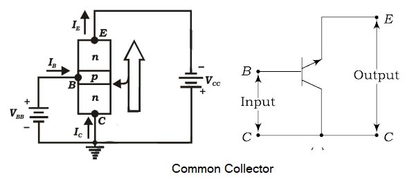
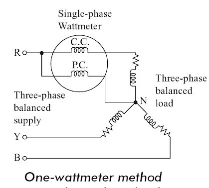
Ques 29. The one wattmeter method of 3-φ measurement can only be used for
- Unbalanced Load
- Balanced Load✓
- Balanced Star connected load
- Balanced delta connected load
In this method, only one single-phase wattmeter can be used to measure the total three-phase power. this method, the current coil (CC) of the wattmeter is connected in series with any phase and the pressure coil (PC) is connected between that phase and the neutral as shown in Fig. The one-wattmeter method has a demerit that even a slight degree of unbalance in the load produces a large error in the measurement. ln this method one wattmeter will measure only the power of one phase. Hence, the total power is taken as three times the wattmeter reading. Total Power = 3 × Vph. Iph. cosφ Note:- The two and three-wattmeter method can be used for balanced as well as unbalanced load.One-wattmeter Method
Ques 30. Phase Voltage and current of a 3Φ, three-wire star-connected system, with an inductive load of power factor 0.707 (lag), is 150 V and 30√3 A. If the power in the system is being measured using two wattmeters the difference in meter readings is:
- 9.54 kW✓
- 10.46 kW
- 3.95 kW
- 2.26 kW
In star connected system the Line voltage is root three times the phase voltage and line current remain same as the phase current VL = √3 Vph VL = √3 × 150 IL = Iph IL = 30√3 According to two wattmeter method ⇒ Reading of wattmeter 1 ⇒ Reading of wattmeter 2 ⇒ Sum of the two wattmeter W1 + W2 = √3VL IL cosφ ⇒ Difference of the two wattmeter W1 − W2 = VL IL sinφ Hence √3 × 150 × 30 × √3 × 0.707 W1 − W2 = 9544.5 W W1 − W2 = 9.54 kW
W1 = VL IL cos (30 − φ)
W2 = VL IL cos (30 + φ)

