Ques 31. Which of the following material is used as the arc quenching medium in high Rupturing Capacity (HRC) fuse?
- Argon Gas
- Plaster of Paris✓
- Mica
- Aluminum
HRC Fuses High rupturing capacity (HRC) Fuse links provide complete protection to cables, switchgear, control gear and other equipment by limiting the current, both in magnitude and in the time duration, that can pass through these devices in the circuit. The rapid operation in the event of a fault limits the let-through current and energy, thus minimizing the electromagnetic and thermal stresses on the electrical apparatus. These type of fuses comprises a high-grade ceramic body within which fuse elements are placed and welded to the endplates. The assembly is filled with dry granular quartz sand, plaster of Paris, quartz, chalk, marble, dust and cooling mediums, etc. In the event of flow of high short circuit current, this quartz sand solidifies forms high resistance glass in the arc path to ensure effectively are quenching in optimum time. The fuse elements are the non-deteriorating type which means that they maintain their characteristics over the long service period. The fuse element is either pure silver or bimetallic in nature. Silver-plated tag contacts provide good contact with the fuse base and keep the fusing temperature low. These types of fuses can be plugged in and out even when hot or in service with an insulated fuse puller. The fuse element in the form of a long cylindrical wire is not used because after melting, it will form a string of droplets and an arc will be struck between each of the droplets. The shape of the fuse element depends upon the characteristic desired. When the fuse carries a normal rated current, the heat energy generated is not sufficient to melt the fuse element. But when a fault occurs, the fuse element melts before the fault current reaches its first peak. As the element melts, it vaporizes and disperses. Advantages of HRC Fuses Disadvantages of HRC Fuses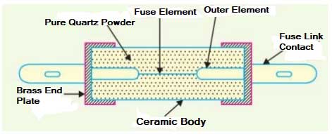
Applications of HRC Fuses
Ques 32. In steam power stations, the condenser creates a _______ at the exhaust of the turbine.
- Very low pressure✓
- Very High Pressure
- Very high temperature
- Very low temperature
The steam power plant is also called the thermal power plant. It is an important source to produce electricity. The major portion of electricity demand is fulfilled by the steam power plant. In a steam power plant cycle, the turbine is the unit at which the steam gets expanded from high pressure to low pressure. At the exit of the turbine, the pressure is too low and is below atmospheric which cannot be handled directly. Hence the exit of the turbine cannot be open to the atmosphere. In order to handle the low-pressure steam, an additional unit called the condenser is used in steam power plants. A steam condenser is a closed vessel in which the steam after doing useful work in the turbine is condensed and the pressure is maintained below atmospheric pressure is vacuum pressure. The condensed steam is called condensate and it possesses a considerable amount of liquid enthalpy. The basic diagram of the steam turbine is shown below. The function of a condenser in steam plant A condenser does the job of condensing the steam exhausted from the turbine. Thus, it helps in maintaining low pressure (below atmospheric) at the exhaust, thereby permitting expansion of steam in the turbine to very low pressure. This improves plant efficiency. The exhaust steam is condensed and used as feed water for the boiler. Maintenance of a high vacuum in the condenser is essential for efficient operation. Any leakage of air into the condenser destroys the vacuum. As it is not possible to eliminate the air leakage completely, a vacuum pump is necessary to remove the air leaking into the condenser. Modem power plants mostly use surface condensers. A surface condenser consists of an airtight cylindrical shell having a chamber at each end. Water tubes extend between the chambers. The shell is made of welded steel (plate construction) and the tubes are made of copper-zinc alloy. Cooling water flows through the tubes. The steam is admitted from the top which gets condensed due to contact with the tube surfaces. The condensate leaves from the bottom. For efficient operation, the temperature rise in cooling water passing through the condenser should be around 10°C. FUNCTION OF CONDENSER The following are the main functions of a typical condenser in a steam power plant. NECESSITY OF A CONDENSER IN A STEAM POWER PLANT Due to the following advantages of the condenser, we can justify that the condensers are necessary for a steam power plant.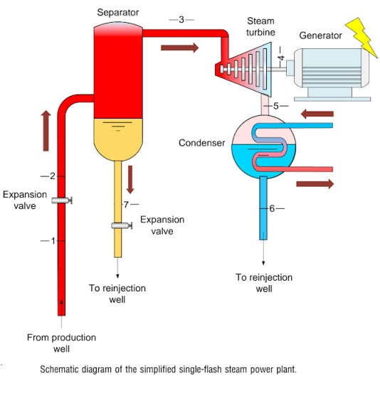
Ques 33. A DC generator having 2 layer lap winding is wound with 4 poles and 18 coils. The pole pitch in this case is
- 7
- 8
- 36
- 9✓
Pole pitch = slots/pole Number of commutator segments = 18 Number of conductors or coil side = 18 x 2 = 36 Pole pitch = 36/4 = 9
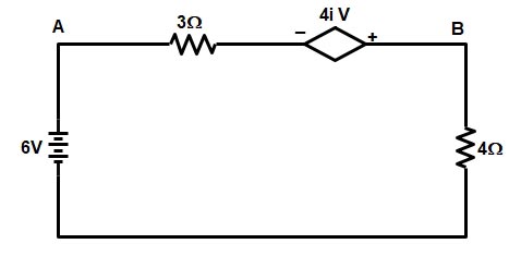
Ques 34. For the given circuit the current through 3Ω resistance is
- 3 A (from A to B)
- 3.5 A (from B to A)
- 2 A (from A to B)✓
- 1.7 A (from B to A)
Applying KVL on the given circuit we get 6 = 3i − 4i + 4i i = 2A The movement of current is assumed as positive to negative direction hence the current flows from (A to B) i = 2 A (from A to B)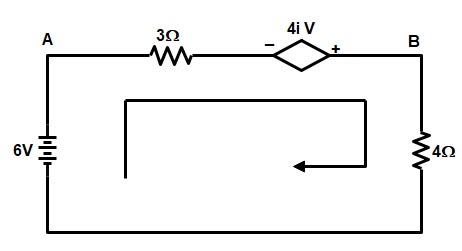
Ques 35. In 3-φ measurement for a balanced load using the two-wattmeter method, the reactive power is given by
- √3 times the sum of the reading of the two wattmeter✓
- The sum of both the wattmeter reading
- √3 times the difference in the reading of the two wattmeter
- 3 times the difference in the reading of the two wattmeter
As the tangent of the angle between phase current and phase voltage of a circuit is always equal to the ratio of reactive power to the true power (Fig.). Hence, in the case of a balanced load, the reactive power is given by √3 times the difference of the readings of the two wattmeters used to measure the power of a 3-phase circuit by the two wattmeter method. Mathematical proof is as follows: Reading of wattmeter 1 ⇒ Reading of wattmeter 2 ⇒ Sum of the two wattmeter W1 + W2 = √3VL IL cosφ——2 Multiplying equation 1 and 2 by √3 √3(W1 + W2) = √3 [VL IL cos (30 − φ) − VL IL cos (30 + φ)] = √3 VL IL(cos30° cosφ + sin30° sinφ) − (cos30° cosφ − sin30° sinφ) = √3 VL IL(cos30° cosφ + sin30° sinφ − cos30° cosφ + sin30° sinφ) = √3 VL IL(2 sin30° sinφ) = √3 VL ILsinφ √3(W1 + W2) = √3VL ILsinφ Thus it is proved above that the reactive volt-amperes of a 3 phase circuit can be obtained by multiplying the difference of two wattmeter readings by √3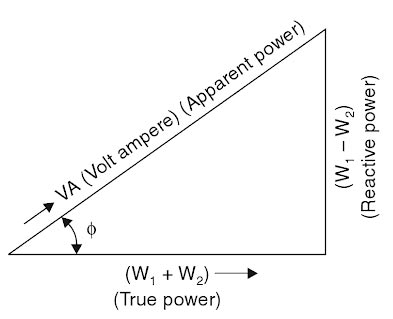
W1 = VL IL cos (30 − φ) —–1
W2 = VL IL cos (30 + φ)
Ques 36. The fluorescent tube of 20 W has the luminous flux of
- 950 lumen✔
- 14 lumen
- 50 lumen
- 325 lumen
Luminous efficiency is defined as the output in lumens per watt of the power consumed by the source of the light. For fluorescence lamp luminous efficiency is 40 – 90 lumens/watt. The luminous flux ΦV in lumens (lm) is equal to the power P in watts (W), times the luminous efficacy η in lumens per watt (lm/W): ΦV(lm) = P(W) × η(lm/W) So lumens = watts × (lumens per watt) The luminous flux between minimum to maximum range luminous flux = watts × (lumens per watt) luminous flux = 20 × 45 = 900 lumen & luminous flux = 20 × 90 = 1800 lumen So a 20 Watt tube should produce between 900 – 1800 lumens. Hence option A i.e 950 lumens is right option
Ques 37. A room measuring 12 × 20 feet is illuminated by 12 lamps rated 100 watts each with an efficiency of 12 lumens/watt. Assuming a depreciation factor of 1.5 and coefficient of utilization of 0.5, the illumination at the plane of the room is
- 48.36 lumen/ft2
- 23.48 lumen/ft2
- 16.67 lumen/ft2
- 37.54 lumen/ft2
Ques 38. The magnitude of flux in a magnetic circuit may be calculated as
$\begin{array}{l}1.\dfrac{{NIl}}{{\mu A}}\\\\2.\dfrac{{NI}}{{\left( {\dfrac{l}{{\mu A}}} \right)}}\\\\3.\dfrac{{NI\mu }}{{\left( {\dfrac{A}{l}} \right)}}\\\\4.\dfrac{{NI}}{l}\end{array}$
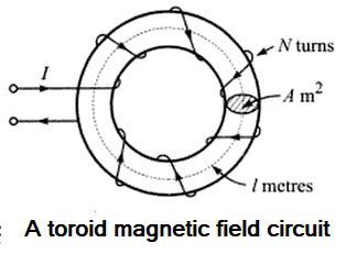
MAGNETIC FLUX The magnetic field may be regarded as a field of induction or flux on account of the induced magnetism experienced by any material placed in that field, due to the magnetization force present. The notion of magnetic flux has to be distinguished from the notion of magnetic force. The conception of lines of magnetic induction or lines of magnetic flux is used to show the direction of the magnetic flux at any point in the field. The symbol for magnetic flux is so, and it is measured in terms of the unit called Weber. The amount of magnetic flux per metre2 over a small area (the area being in the position which gives a maximum value for the flux) is known as the magnetic flux density. The symbol for flux density is B. B = φ/A Weber/metre2 Where Φ = magnetic flux B = Flux density Note: Flux lines of a magnetic field always form closed loops. Magnetic field Intensity (H) is also called Magnetic field Strength, Magnetic Intensity, Magnetic field, Magnetic Force and Magnetization Force. Magnetic Field Strength (H) gives the quantitative measure of the strongness or weakness of the magnetic field. Suppose that a current of I amperes flows through a coil of N turns wound on a toroid of length I meters. The MMF is the total current linked to the magnetic circuit i.e IN ampere-turns. If the magnetic circuit is homogeneous and of a uniform cross-sectional area, the MMF per meter length of the magnetic circuit is termed the magneticfield strength, magnetic field intensity, or magnetizing force. It is represented by the symbol H and is measured in ampere-turns per meter (At/m). H = IN ⁄ L Relation Between Magnetic Flux Density and Field Intensity At any point in a magnetic field, field strength or field intensity H is the force maintaining the magnetic flux and producing a particular value of flux density B at that point. Hence the field intensity H is the cause and the flux density B is the effect. Thus the flux density can be assumed proportional to field intensity in the magnetic field i.e. in free space, B = μoH where μo is called the permeability of free space or magnetic space constant. Its value is 4π × 10-7 H/m, Now put the value of flux density and field intensity in Eqn 1 φ ⁄ A = μoIN ⁄ L φ = μoINA ⁄ L
A = Surface area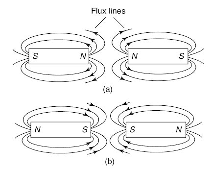
Ques 39. The term “permeance” in a magnetic circuit is analogous to _______ in an electric circuit.
- Impedance
- Reluctance
- Conductance✓
- Susceptance
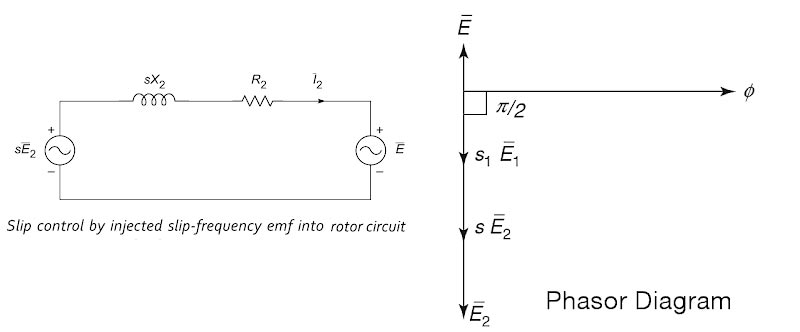
Ques 40. In the method of speed control of an induction motor by inducing EMF in the rotor circuit, if the injected voltage is in the phase opposition to the induced rotor EMF, then
- The rotor resistance Increase✓
- The rotor reactance increase
- The rotor reactance decrease
- The rotor resistance decrease
Speed control of Induction motor by injecting SLip Frequency E.M.F. into Rotor Circuit In this method, a voltage is injected into the rotor circuit. The frequency of the rotor circuit is a slip frequency and hence the voltage to be injected must be at a slip frequency. It is possible that the injected voltage may oppose the rotor induced e.m f. or may assist the rotor induced e.m.f. Since the speed of the rotating magnetic field in the space is equal to the slip sliced, the emf induced to the secondary (stator) also corresponds to the slip frequency. The voltage injected into the stator winding will always be at the slip frequency when the brushes are connected to the stator windings. It is possible to adjust the phase of the voltage injected into the secondary winding, that is, the stator is either in-phase or antiphase (out of phase) with the stator-induced voltage. The figure shows the phasor diagram of the emf injected into the secondary. Let us consider the following: E2, be the magnitude of standstill secondary voltage, s be the no-load slip at the motor, E be the magnitude of the voltage injected into the motor secondary and s1 be the new operating slip after injecting the voltage. If the injected voltage is in phase opposition to E2, the resultant voltage in the rotor circuit become s1E2 − E. as shown in fig. We have the following expression for the new slip s1 Initially, the speed cannot change due to the inertia of the rotor, the net emf in the rotor circuit reduces to a value (s1E2 − E), as a result of which the rotor current I, and, hence, the torque developed decreases. But, since the load “torque remains constant, the speed of the motor starts decreasing. This process of reduction in speed (increase in slip and resistance) continues till the rotor induced emf increases to circulate enough current in the rotor to develop the desired torque. sE2 = s1E2 − E s1E2 = sE2 + E or s1 = s + E/E2 i.e. when the emf injected is in phase opposition to the rotor induced emf, the slip increases or the speed of the motor decreases. By similar reasoning, it is easy to observe that when the injected emf is in phase with the rotor induced emf, the slip and resistance decrease or the speed of the motor increases. Eqn., under such conditions, will be expressed as s1 = s + E/E2 Thus by controlling the magnitude of the injected e.m.f., rotor resistance and effective speed can be controlled. Practically two methods are available that use this principle. These methods are, 1. Kramer system 2. Scherbius system