
Ques 41. In case of an alternator connected to an infinite bus, the active power can be varied by
- Changing the prime mover speed✓
- Changing the power factor
- Changing the field excitation
- Changing both prime mover speed and field excitation
Ques 42. The circuit whose properties or characteristics changes with the direction of its operation is
- Unilateral✓
- Bilateral
- Linear
- Non-Linear
A unilateral circuit is one whose properties or characteristics change with the direction of the operatic For example, in the diode circuit, the characteristic is different in the forward and reverse direction. Thus a unilateral circuit, the properties or the characteristics are unique in a particular direction of operation. A bilateral circuit is one whose properties or characteristics are the same in either direction. For example, in a resistive circuit, the current through a resistance is not affected by the direction of current flow. Linear circuit. A linear circuit is one in which the values of the circuit parameters or components, that is, the resistance, capacitance, inductance, gain, etc. do not change with the level of voltage or current in the circuit. A linear circuit obeys the principle of superposition. Non-linear circuit. A circuit whose parameters change with the application of voltage or current is called a non-linear circuit. Examples of the non-linear behavior of circuit elements and circuits are diodes, transistors in the saturated region, saturated iron core inductors and transformers, modulators, and digital logic circuit Non-linear circuits are analyzed using approximate numerical methods by electronic circuit simulati~ computer programs such as spice, for accurate results.
Ques 43. The de-ionization of the medium in the current zero methods of an arc extinction is NOT achieved by
- Splitting the arc✓
- Lengthening of the gap between the contacts
- Increasing the pressure of the vicinity of the arc
- Cooling the arc
After the occurrence of the fault, when the contacts of the CB begins to separate an arc is established in the contact gap. The two main causes responsible for generating arc between the contacts of a CB are as follows: Potential difference (PD) between the contacts: When the contacts have a small separation, the PD between them is sufficient to maintain the arc. One way to extinguish the arc is to separate the contacts to such a distance that PD becomes inadequate to maintain the arc. However, this method is impracticable in high voltage systems where separation of many meters may be required. Ionized particles between contacts: The ionized particles between the contacts tend to maintain the arc. If the arc path is deionized, the arc extinction will be facilitated. This may be achieved by cooling the arc or by bodily removing the ionized particles from the space between the contacts. Methods of Arc Extinction There are two methods of extinguishing the arc in CB viz. In this method, arc resistance is made to increase with time so that the current is reduced to a value insufficient to maintain the arc. Consequently, the current is interrupted or the arc is extinguished. The principal disadvantage of this method is that enormous energy is dissipated in the arc. Therefore, it is employed only in DC CBs and low-capacity AC CBs. The resistance of the arc may be increased by: Low Resistance or Current Zero Method This method is employed for arc extinction in AC circuits only. In this method, arc resistance is kept low until the current is zero where the arc extinguishes naturally and is prevented from restriking in spite of the rising voltage across the contacts. All modern high-power AC CB employ this method for arc extinction. In an AC system, the current drops to zero after every half cycle. At every current zero, the arc extinguishes for a brief moment. Now the medium between the contacts contains ions and electrons so that it has a small dielectric strength and can be easily broken down by the rising contact voltage known as restriking voltage. If such a breakdown does occur, the arc will persist for another half cycle. If immediately after current zero, the dielectric strength of the medium between contacts is built up more rapidly than the voltage across the contacts, the arc fails to restrike and the current will be interrupted. The rapid increase of dielectric strength of the medium near current zero can be achieved by
Ques 44. In the process of nickel plating of iron particles, iron will first be applied with a film of ______ to ensure good quality
- Aluminum
- Chromium
- Copper✓
- Silver
The term electroplating refers to the deposition of a metal onto the surface of another metal, alloy, or any conductor in general, by the process of electrolysis. It consists of a process, by which a metal is deposited on another metal or alloy by passing a direct current through an electrolyte solution containing the metal ions to be deposited. Therefore, electroplating can be defined as “a process in which a base metal is coated with a thin and uniform layer of another suitable metal by electrolytic deposition”. The common coating metals used are Zn, Cu. Ni, Cr. Ag, Pt. Au, etc. Electrodeposition is an important and frequently used method in industries for metal coating. Electroplating is a process of a continuous flow of ions, which is not possible in an Alternating current(due to changing in polarity very frequently) so the continued deposition of cation does not occur. The process involves the electroplating is:- Nickel plating is an electrolytic process whereby a thin layer of nickel is deposited on the surface of a metal item by means of a low voltage electric current. If an item to be Electro-plated is iron or steel it is usually copper plated first to enhance the cohesion of the nickel to the article. Although Chromium plating is also adopted to protect the iron. However, the plated chromium metal is brittle and hence cracks and peels off. Therefore iron is first plated with copper, then with nickel, and finally with chromium. Copper gives good adhesion, nickel affords protection and chromium enhances the appearance. The composite coating is hard and highly resistant to corrosion.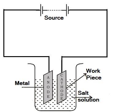
Process Involve in electroplating
Ques 45. In the method of synchronization of an alternator to the bus bar, a Synchroscope indicates the correct speed when
- The pointer moves towards Left
- The pointer moves towards Right
- The pointers move vertically up✓
- The pointers vibrate at the center
A synchroscope is a device that produces a revolving field proportional to the speed difference between the incoming machine and the system. It is constructed so that the angular phase difference is indicated on the synchroscope dial. or A synchroscope indicates when two AC generators are in the correct phase in relation to connecting in parallel and shows whether the incoming generator is running faster or slower than the on-line generator. The synchroscope measures the difference in voltage and frequency of the two alternators. The pointer of the synchroscope is free to rotate in a 360° arc. The alternator already connected to the load is considered to be the base machine. The synchroscope indicates whether the frequency of the alternator to be parallel to the base machine is fast or slow. When the voltages of the two alternators are in phase, the pointer covers the shaded area on the face of the meter. When the two alternators are synchronized, the synchronizing switch is closed. The voltage from one phase of the three-phase bus bar system is connected to one set of synchroscope coils. The voltage from the same phase of the incoming alternator is connected to another set of synchroscope coils. A pointer is attached to the synchroscope rotor and rotates over a dial face.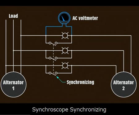
Ques. 46 While measuring the insulation resistance of complete wiring installation to earth using Megger, the resistance measured must not be less than
- 500 MΩ ⁄ Number of outlets(points + switches)
- 50 MΩ ⁄ Number of outlets(points + switches)✓
- 50 KΩ ⁄ Number of outlets(points + switches)
- 25 KΩ
Testing of Insulation Resistance of Complete Installation to Earth The principal purpose of testing the insulation is to verify that there are no inadvertent connections between live conductors and between live and Earth before the installation is energized. Tests are required between live conductors (e.g. between phases and between phase(s) and neutral) and between all live conductors and Earth. Insulation resistance of the installation depends on many factors such as atmospheric conditions, humidity, dirt, etc. As such its calculation is not possible, but it can be readily measured. Normally the insulation resistance is quite high and can be measured by an instrument called megger; usually used for the measurement of high resistance. The main object in performing this test is to ascertain whether the complete wiring is sound enough to avoid leakage current. As per the Indian electricity rules, the leakage current of an installation should not exceed 1/5000 of the maximum supply-demand of the consumer. As such the insulation resistance of the complete installation to earth should not be less than 1 MΩ. Insulation resistance test must be conducted on dc voltage of value not less than twice the standard supply voltage. However, it does need not exceed 500 V for medium voltage circuits. Insulation resistance of the installation to earth is measured by a megger generating dc voltage of about 500 V. Insulation resistance is measured under the following conditions. (i) Main switch in off position. (ii) The main fuse to be taken out. (iii) All other fuses to be provided. (iv) All lamps must be put in the on position. (v) All switches must be made on. (vi) Live and neutral wire to be shorted together. Testing of Insulation Resistance Between Conductors After testing the insulation resistance of installation to earth, the insulation resistance between line and neutral should be measured. The major object in conducting this test is again to ensure that the insulation is quite sound between the conductors and there are no chances of an appreciable leakage current between them. This test should be carried out under the following conditions of installation (i) Main switch off. (ii) the Main fuse is withdrawn. (iii) All other fuses in their position. (iv) All switches in on position. (v) All lamps from the holders were removed. (vi)Two terminals of the meager are connected to the line and neutral wire. Insulation resistance measured under the above condition by a megger should not be less than 50 MΩ divided by the number of outlets(points + switches). However, it need not be more than 1 MΩ.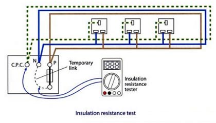
Ques 47. The reluctance of a straight magnetic path
- Directly proportional to the permeability
- Inversely proportional to the length
- Directly proportional to the area✓
- Inversely proportional to the area
RELUCTANCE Flux in a magnetic circuit also depends on the opposition that the circuit presents to it. Reluctance (RM), is the opposition a magnetic circuit offers to the formation of magnetic flux. The opposition depends on the dimensions of the core and the material of which it is made. Like the resistance of a wire, reluctance is directly proportional to length (L) and inversely proportional to cross-sectional area (A). In equation form, RM = L/A (Ampere-Weber) The unit of Reluctance is Ampere-Weber or A/Wb To change the ‘proportional’ sign into an ‘equals’ sign we must introduce a constant. This constant is called ‘magnetic reluctivity‘ and is directly equivalent to resistivity in an electric circuit. However, it’s far more common to use it’s reciprocal instead, which we call ‘absolute permeability(μ)‘ Which is equivalent to conductivity. Permeability is a measure of how easy it is to establish the flux in a material. Ferromagnetic materials have high permeability and hence low RM, while nonmagnetic materials have low permeability and high RM. RM = L/μA
Ques 48. Which of the following is NOT an advantage of the stationary armature in a synchronous machine.
- The slip ring get transferred to the low power DC circuit
- It becomes easy for the armature to carry the stator flux✓
- It becomes easier to insulate the armature winding
- The output voltage can be directly connected to the load without brushes
FIELD AND ARMATURE CONFIGURATIONS There are two arrangements of fields and armatures: In large alternators, the rotating field arrangement is usually forward due to the following advantages. Due to the armature is stationary the phenomenon of armature reaction takes place in an alternator Armature Reaction When the load is connected to the alternator, the armature winding of the alternator carries a current. Every current-carrying conductor produces its own flux so the armature of the alternator also produces its own flux when carrying a current. So there are two fluxes present in the air gap, one due to armature current while the second is produced by the field winding called main flux. The flux produced by the armature is called armature flux. Hence it is not easy for the armature to carry stator flux due to armature reaction.
ADVANTAGES OF ROTATING FIELD IN AN ALTERNATOR
Ques 49. Which of the following can be used as the dopant to make N-type semiconductor?
- Boron
- Aluminum
- Arsenic✓
- Indium
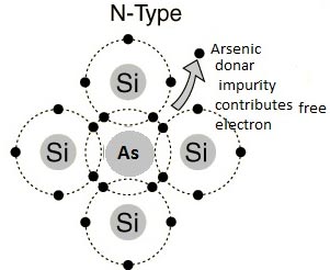
Extrinsic Semiconductor In order to change the properties of intrinsic semiconductors a small amount of some other material is added to it. The process of adding other material to the crystal of intrinsic semiconductors to improve its conductivity is called doping. The impurity added is called dopant. The doped semiconductor material is called extrinsic semiconductors. The doping increases the conductivity of the basic intrinsic semiconductors hence the extrinsic semiconductors are used in practice for the manufacturing various electronic devices such as diodes, transistors, etc. Depending upon the type of impurities, the two types of extrinsic semiconductors are, N-TYPE Impurity The impurity material having five valence electrons is called the pentavalent atom. When this is added to an intrinsic semiconductor, it is called donor doping as each impurity atom donates one free electron to an intrinsic material. Such an impurity is called donor impurity. Examples of such impurities are arsenic, bismuth, phosphorous, Antimony, etc. This crests an extrinsic semiconductor with a large number of free electrons called an n-type semiconductor. Germanium and Silicon are tetravalent. The impurity atoms may be either pentavalent or trivalent, i.e., from groups V and III of the periodic table. If a small quantity of a pentavalent impurity (having 5-electrons in tt outermost orbit) like Arsenic (As), Antimony (Sb), or Phosphorus (P) is introduced in Germanium, it replaces the equal number of Germanium atoms without changing the physical state of the crystal. Each of the four out of five valency electrons of impurity says Arsenic enters into covalent bonds with Germanium, while the fifth valence electron is set free to moo from one atom to the other as shown in Fig. The impurity is called donor impurity as it donates an electron and the crystal is called an N-type semiconductor. A small amount of Arsenic (impurity) injects billions of free electrons into Germanium thus it creasing its conductivity enormously. In an N-type semiconductor, the majority carriers of charge are the electrons and holes as minority carriers. This is because when donor atoms are added to a semiconductor, the extra free electrons give the semiconductor a greater number of free electrons than it would normally have.
Ques 50. The direction of rotation of split-phase motor can be reversed by
- By reversing either auxiliary Terminal or main terminal✓
- By reversing the supply terminal
- By reversing the auxiliary Terminal only
- By reversing the main terminal

