Ques 11. The function of a conservator in a transformer is to:
Store extra oil to use in emergency
Prevent entry of moisture
Cool transformer
Take care of expansion and contraction of oil due to change in temperature oil✓
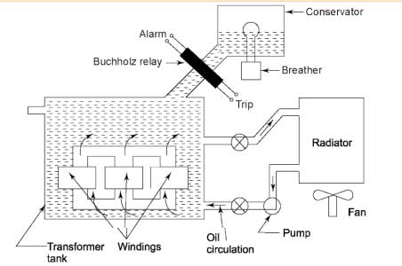
The conservator is a cylindrical tank mounted on a supporting structure on the roof of the transformer’s main tank.
The satisfactory operation of a transformer solely depends on the condition of the oil. The oil should not be allowed to come in contact With atmospheric air as it may take up moisture which may spoil the insulating properties. Also, air may cause acidity and sludging of oil. To prevent this, many transformers are provided with conservators. The function of a conservator is to take up contraction and expansion of oil without allowing it to come in contact with outside air.
With the rise of temperature, the oil level increases. The rise of temperature depends on the load of the transformer. If the load increases, the oil expands. If the load decreases, contraction of oil occurs. The conservator is partially filled with the oil.
When the volume of transformer insulating oil increases due to load and ambient temperature, the vacant space above the oil level inside the conservator is partially occupied by the expanded oil. Consequently, the corresponding quantity of air in that space is pushed away through the breather. On other hand, when the load of the transformer decreases, the transformer is switched off, and when the ambient temperature decreases, the oil inside the transformer contracts. This causes outside air to enter the conservator tank of the transformer through a silica gel breather.
Ques. 12 A 3-phase 440 Volt, 50 Hz induction motor has a slip of 5%. The frequency of rotor EMF is
50 Hz
5 Hz
2.5 Hz✓
None of these
Rotor frequency is given as the slip times the stator frequency.
fr = sfs = 0.05 x 50 = 2.5 Hz
Ques 13. A diode is forward biased if.
The anode is positive with respect to the cathode✓
The cathode is positive with respect to the anode
Anode and cathode are at the same polarities
None of the above
A diode is a two-electrode (two-terminal) device that acts as a one-way conductor. The most basic type of diode is the PN-Junction diode. When forward bias PN junction diode conducts. When reverse biased, it effectively blocks the flow of charge (current).
A diode permits current Bow when the voltage on the anode is positive with respect to the voltage on the cathode.
A diode inhibits current flow when the voltage on the anode negative with respect to the voltage on the cathode.
A diode is called forward biased when the anode is positive with respect to the cathode. A forward-biased diode functions like a closed switch permitting current flow. A diode is called reversed biased when the anode is negative with respect to the cathode. A reversed biased diode functions like an open switch inhibiting current flow.
Based on the characteristics of a switch the following statements can be considered about the ideal diode:
When forward-biased enclosed switch):
The diode has no resistance.
The diode does not limit the circuit current
The diode has no voltage drop across its terminals.
When reverse biased (open switch):
The diode has infinite resistance.
The diode does not pass current.
The diode drops the applied voltage across its terminals.
Ques 14. Which of the following is the correct expression of Power factor?
Apparent Power/True Power
True Power/Apparent Power✓
Reactive power/True power
Apparent/Reactive Power
There are many ways to understand POWER FACTOR
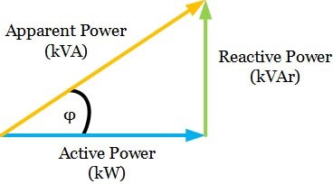
⇒ One definition expresses power factor as the cosine of the phase displacement angle between the circuit voltage and current.
CosΦ = V/I
⇒The other definition is that the power factor is the ratio of active power to apparent power in a circuit. It is generally given in percent. Most utilization devices require two components of current, active and reactive.
The power-producing current (active current) is the current that is converted by the equipment into work, usually in the form of heat, light, or mechanical power.
The unit of active power is the watt. The magnetizing current (reactive current) is the current required to produce the flux necessary to the operation of electromagnetic devices. The unit of reactive power is the var.
Ques 15. A single-phase transformer has 400 turns on primary and 50 turns on the secondary, the cross-sectional area of the core is 80cm2 and flux density is 12wb/cm2, if a 440 volt 50 Hz AC supply is given to the primary side, What will be the induced EMF and frequency on the secondary side of the transformer?
50 Volt. 50 Hz
55 volt, 50 Hz✓
75 volt, 25 Hz
None of these
The transformer is the static device that is used to transfer electricity from one AC circuit to the other AC circuit, by either increasing or decreasing V or I.
As the supply frequency to the transformer causes the production of alternating flux in the core and the same flux links with the secondary winding, the frequency of flux and hence the mutually induced emf in the secondary remains the same as that of the primary winding supply frequency.
Hence whatever is the supply frequency at the input of the transformer same as the value of output voltage of the transformer.
Ques 16. A ceiling fan draws a current of 0.5A at a voltage of 220 Volts and has the power factor of 0.8 lagging. What is the power of the fan?
98 watt
88 Watt✓
78 Watt
None of these
The average power in an AC circuit expressed in terms of the RMS voltage and current is;
Pavg = V x I x cos ø
Where ø is the phase angle between the voltage and current. And ‘cos ø’ is called the Power Factor (PF).
P = 220 x 0.5 x 0.8 = 88 Watt
Ques 17. MCB protects a circuit from
Short circuit
Over Load only
Both short circuit and overload✓
None of the above
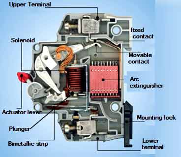
Miniature Circuit breaker (MCB)
This is an electro-mechanical device that breaks (that is, opens) the circuit when the current in it exceeds a given value. Unlike fuses, which melt at 50% to 100% overload, MCBs break the circuit at just 5% to 15% overload and thus provide better safety. Note that an MCB protects the circuit against both overloads and short-circuits.
An MCB incorporates a thermal and magnetic tripping device. The load current flows through the thermal and electromagnetic mechanisms. In normal operation, the current is insufficient to operate either device, but when an overload occurs, the bimetal strip heats up, bends, and trips the mechanism. The bimetallic strip is made up of copper and iron pasted together.
A bimetallic strip is used to convert a temperature change into mechanical displacement. The time taken for this action to occur provides an MCB with the ability to discriminate between an overload that persists for a very short time, for example, the starting current of a motor, and an overload due to a fault.
The device only trips when a fault current occurs. This slow operating time is ideal for overloads but when a short circuit occurs it is important to break the faulty circuit very quickly. This is achieved by the coil electromagnetic device.
(b) To prevent high short-circuit current from damaging circuit elements, the MCB is also provided with a magnetic coil and plunger (known as the solenoid ). At normal operating conditions, the electromagnet is not strong enough to release the contact.
When the short circuit occurs in the circuit, the current energizes the solenoid which attracts the plunger which strikes the trip lever, and immediately releases the latch mechanism to open the contacts. The instantaneous opening of contacts is achieved due to the rapid operation of the solenoid.
Ques 18. The current density of a conductor of a large cross-sectional Area when the same current is flowing through them
Greater Than
Less than✓
Equal to
None of these
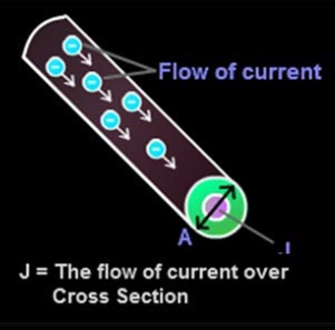
The amount of electric current traveling per unit cross-section area is called current density and expressed in amperes per square meter. The more the current in a conductor, the higher will be the current density.
The formula for Current Density is given as,
J = I / A
Where,
I = current flowing through the conductor in Amperes
A = cross-sectional area in m2.
Current density is expressed in A/m2.
From the above relation, it is clear that the current density is inversely proportional to the cross-sectional area so the larger the cross-sectional area less will be the current density.
Ques 19. How is an electric element capacitor is specified?
Ohmic value and voltage
Ohmic value and Wattage
Voltage and capacitance✓
Wattage and capacitance
Electrical elements are conceptual abstractions representing idealized electrical components, such as resistors, capacitors, and inductors, used in the analysis of electrical networks.
Capacitance is defined as that a capacitor has the capacitance of One Farad when a charge of One Coulomb is stored on the plates by a voltage of one volt.
C = Q/V
So the capacitor can be specified by Voltage, Capacitance, and Charge(coulomb).
Capacitance is the ratio of the change in an electric charge in a system to the corresponding change in its electric potential.
Ques 20. Which of the following connection is best suited for 3-phase, 4 wire service:
Δ − Δ
Δ − Y✓
Y − Y
Y − Δ
3-phase, 4 wire service is used in a distribution transformer. In 3 phase 4 wire system, neutral wire carries return current in case any fault occurs in the line there is more flexibility to keep the system running since it may only affect one of the phases.
In star connection, line and phase currents are the same but the line voltage is √3 times the phase voltage. In the delta connection, line and phase voltages are the same but the line current is √3 times the phase current. However, the power in both connections is the same, that is
√3VLIL cosφ.
In delta connection
The delta connection is used for transmission purposes because, In a 3-phase, delta-connected system, no wire exists for the return current i.e there is no neutral point, also the line current gets divided by √3 and hence the cross-sectional area of the conductor to be used in each of the three phases of the primary winding will be reduced. Thus saving of copper.
Delta connection provides a path for the third-order harmonic current and hence no distortion because of it
The star connection is used for distribution purposes because the star connection has neutral point and the neutral wire carries a return current in case of any fault occurs in the line there is more flexibility to keep the system running since it may only affect one of the phases.
Hence the primary is connected to the delta and the secondary is connected to the star. The main use of this connection is to step up the voltage i.e. at the beginning of the high tension transmission system. As the secondary side is star connected, the use of a three-phase, four-wire system is possible. Thus single-phase and three-phase loads can be supplied with this type of connection.
Ques 21. Which type of resistor is used for overvoltage protection:
Sensors
Thermistors
Varistors✓
Inductor
“Varistor” is the generic name for a voltage-variable resistor. These devices obey the relations V = (I x R). where R is a function of V or I, and for which R decreases as the magnitude of V (or I) increases. A Varistor is inherently a non-linear bipolar device: its characteristics are not dependent on polarity.
Surge protection devices are used widely to protect electric devices from destruction by an over-voltage such as lightning and electrostatic. A typical surge protection devices are an arrestor which is put on the top of the telephone pole and a metal oxide varistor which is used in small-scale circuits. These devices have a non-linearity correlation between voltage and current. When a transient occurs, the varistor resistance changes from a very high stand-by value to a very low conducting value. The transient is thus absorbed and clamped to a safe level, protecting sensitive circuit components.