Ques 22. Which of the following relation is correct?
Flux = mmf × reluctance
Conductivity = 1/resistivity✓
Permeability = 1/reluctivity✓
None of these
Electrical conductivity or specific conductance is the reciprocal of electrical resistivity and measures a material’s ability to conduct an electric current.
In electromagnetism, permeability is the measure of the ability of a material to support the formation of a magnetic field within itself. Hence, it is the degree of magnetization that a material obtains in response to an applied magnetic field.
A measure of the resistance of a material to the establishment of a magnetic field within it is equal to the ratio of the intensity of the magnetic.
The tendency of a magnetic circuit to conduct magnetic flux equal to the reciprocal of the permeability of the circuit.
In other words: In magnetic circuits, we have specific reluctance which is also, called reluctivity. The reluctivity is the reciprocal of permeability
Ques 23. The rated speed of the induction Motor is 1410 RPM. What is meant by statement slip s=0
The speed of the motor is higher than the synchronous speed
The motor runs at a synchronous speed✓
The motor runs at its rated speed
The rotor is stationary
As we know that the slip of an Induction motor is given as
s = Ns – Nr/Ns
Now if the slip s = 0 =
0 = Ns – Nr/Ns
or Nr = Ns hence the motor runs at the synchronous speed.
Ques 24. Three-phase distribution transformer’s connections are:
Star – Star
Delta – Star
Star – Star
Delta – Star✓
3-phase, 4 wire service is used in a distribution transformer. In a 3 phase 4 wire system, neutral wire carries return current in case any fault occurs in the line there is more flexibility to keep the system running since it may only affect one of the phases.
In star connection, line and phase currents are the same but the line voltage is √3 times the phase voltage. In the delta connection, line and phase voltages are the same but the line current is √3 times the phase current. However, the power in both connections is the same, that is
√3VLIL cosφ.
In delta connection
The delta connection is used for transmission purposes because, In a 3-phase, delta-connected system, no wire exists for the return current i.e there is no neutral point, also the line current gets divided by √3 and hence the cross-sectional area of the conductor to be used in each of the three phases of the primary winding will be reduced. Thus saving copper.
Delta connection provides a path for the third-order harmonic current and hence no distortion because of it
The star connection is used for distribution purposes because the star connection has neutral point and the neutral wire carries a return current in case of any fault occurs in the line there is more flexibility to keep the system running since it may only affect one of the phases.
Hence the primary is connected to the delta and the secondary is connected to the star. The main use of this connection is to step up the voltage i.e. at the beginning of the high tension transmission system. As the secondary side is star connected, the use of a three-phase, four-wire system is possible. Thus single-phase and three-phase loads can be supplied with this type of connection.
Ques 25. Which of the following instrument is used to measure the alternating current only?
Moving – Iron voltmeter
Permanent-magnet type ammeter
Induction type ammeter✓
Moving – iron (attraction – type) ammeter
Moving Iron Voltmeter is used to measure both current and voltage but it can work on both AC and DC.
Moving Iron (attraction – type) ammeter is used to measure both current and voltage but it can work on both AC and DC.
Induction-type instruments are used only for A.C measurement and can be used either as an ammeter voltmeter or wattmeter. However, the induction principle finds its widest application as a watt-hour or energy meter.
Induction type Ammeters and voltmeters are mainly used for the measurement of power and energy in the circuits
An insulation resistance test is a correct term for this form of testing, not a megger test, as megger is a manufacturer’s trade name, not the name of the test.
Types of Cable Faults
Cables are generally laid directly in the ground or in ducts in the underground distribution system. For this reason, there are little chances of faults in underground cables. However, if a fault does occur, it is difficult to locate and repair the fault because conductors are not visible. Nevertheless, the following are the faults most likely to occur in underground cables
Open-circuit fault. When there is a break in the conductor of a cable, it is called an open-circuit fault. The open-circuit fault can be checked by a megger. For this purpose, the three conductors of the three-core cable at the far end are shorted and earthed. Then resistance between each conductor and earth is measured by a megger. The megger will indicate zero resistance in the circuit of the conductor that is not broken. However, if the conductor is broken, the megger will indicate infinite resistance in its circuit.
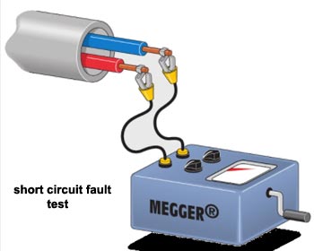
Short-circuit fault. When two conductors of a multi-core cable come in electrical contact with each other due to insulation failure, it is called a short-circuit fault. Again, we can seek help or a megger to check this fault. For this purpose, the two terminals of the megger are connected to any two conductors. If the megger gives zero reading, it indicates a short circuit fault between these conductors. The same step is repeated for other conductors taking two at a time.
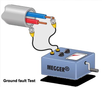
Earth fault: When the conductor of a cable comes in contact with the earth, it is called an earth fault or ground fault. To identify this fault, one terminal of the megger is connected to the conductor, and the other terminal is connected to the earth. If the megger indicates zero reading, it means the conductor is earthed. The same procedure is repeated for other conductors of the cable.
Ques 27. An energy meter has a constant of 600 revolutions per kWh. If the meter makes 10 revolutions in 20 seconds. What is the load in kW?
0.75 KW
1.5 KW
3 KW✓
6 KW
Meter constant K = Number of revolutions Per hour/Electrical energy consumed in kWh
Meter constant = 600 revolution
Meter revolution = 10 revolutions per 20 second, then the number of revolution in 1 hour
= (10 x3600)/20 = 1800 revolution per hour
Electrical energy consumed per hour = number of revolution per hour/Meter constant
= 1800/600 = 3 kW
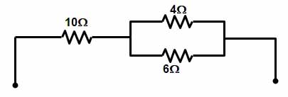
Ques 28. Equivalent resistance point A and B in the following figure is
10 ohm
12.4 ohm✓
6.8 ohm
16 ohm
From the above circuit diagram the resistance 4Ω and 6Ω are connected in parallel therefore equivalent resistance
= 4 × 6/4+6 = 2.4Ω
Now 2.4Ω and 10Ω are connected in series hence total resistance at point A and B is
2.4Ω + 10Ω = 12.4Ω
Ques 29. Which rectifier requires four diodes?
Half wave rectifier
Full Wave Rectifier
Full Wave bridge rectifier✓
Voltage more quadruple
The rectifier in a device converts alternating current into direct current. Rectifier circuits use semiconductor diodes as rectifying elements. Following are the different types of rectifier circuits:
Half-wave rectifier
Full-wave rectifier
The full-wave rectifier can be built in the following ways:
Full-wave rectifier using two diodes and a center-tapped transformer.
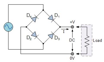
Full-wave bridge rectifier using four diodes and an ordinary transformer.
During the positive half cycle of the supply, diodes D1 and D2 conduct in series, while diodes D3 and D4 are reverse biased and the current, flows through the load as shown below.
During the negative half cycle of the supply, diodes D3 and D4 conduct in series, but diodes D1 and D2 switch “OFF” as they are now reverse biased.
Ques 30. The Sum of all current meetings at a point is zero. Stated law is
Kirchhoff’s first rule✓
Kirchhoff’s third rule
Kirchhoff’s fourth rule
Kirchhoff’s second rule
Kirchhoff’s current law (KCL)
This law is also called Kirchhoff’s first law, Kirchhoff’s point rule, or Kirchhoff’s junction rule (or nodal rule).
The principle of conservation of electric charge implies that:
At any node (junction) in an electrical circuit, the sum of currents flowing into that node is equal to the sum of currents flowing out of that node
i1 + i2 + i4 = i3
or
The algebraic sum of currents in a network of conductors meeting at a point is zero.
The law is based on the conservation of charge whereby the charge (measured in coulombs) is the product of the current (in amperes) and the time (in seconds).
Kirchhoff’s voltage law (KVL)
This law is also called Kirchhoff’s second law, Kirchhoff’s loop (or mesh) rule, and Kirchhoff’s second rule.
The principle of conservation of energy implies that
The directed sum of the electrical potential differences (voltage) around any closed network is zero, or: More simply, the sum of the EMFs in any closed loop is equivalent to the sum of the potential drops in that loop,
V1 + V2 + V3 = V4
The algebraic sum of the products of the resistances of the conductors and the currents in them in a closed loop is equal to the total emf available in that loop.
Ques 31. The R.M.S value of an A.C signal is 10V. Its Peak value will be
6.37 V
14.14 V✓
141 V
None of these
The RMS voltage is given as VRMS = Vpk/√2
VPK = VRMS√2 = 10 x √2 = 14.14
Ques 32. In case of a synchronous motor starts but fails to develop full torque, the probable cause could be:
Low excited voltage
Reverse field winding
Open or short circuit
Any of the above ✓
Low excited Voltage: The starting torque of a synchronous motor is proportional to the square of the applied voltage. When, therefore, a synchronous motor will not start, it may be due to the fact that the voltage on the line is pulled down below the value necessary for starting. If the motor is provided with a starting compensator it may be possible to re-connect the leads and thus obtain a higher terminal voltage. In general, at least half the voltage is required to start a synchronous motor.
Open circuit Line: Difficulty in starting may also be caused by an open circuit in one of the lines to the motor. Assume the motor to be three-phase. If one of the lines is open the motor becomes single-phase, and no single-phase synchronous motor, as such, is self-starting. The motor will, therefore, not start, and will soon get hot.
During the Running conditions, When one line supplying a three-phase motor is open-circuited, a synchronously rotating field will still be produced and the motor will continue to run and provide torque. However, a significant negative phase sequence field will also be produced, which will induce extra losses in the secondary winding and produce an additional Pulsating torque.
Short circuit Line: In case if one of the three phases is short-circuited in the synchronous motor, a large transient current will flow through the motor which may damage the winding of the motor.
If field winding is reversed, here I am assuming that the field winding is fed with AC supply instead of DC supply, because changing the polarity of field winding will make no difference.
The reverse field winding: Fixed excitation in the synchronous machine is given in order to develop the north and south poles respectively after rotating the rotor near or equal to synchronous speed as that of the supply so that the rotor and stator poles will get interlocked with the poles of the stator and the machine will start rotating at the synchronous speed with supply without the need of any prime mover.
Now if we give an ac supply as the excitation :
the north and south pole will generate on the rotor pole alternately changing with supply frequency, hence there can not be an interlocking between the stator and rotor poles and the machine will fail to start.