Copper Losses(or I2R losses and Ohmic Losses) In the primary and secondary Winding. Copper Loss (Pc) has two components. Copper loss in a transformer varies significantly with the load.
Primary Winding copper losses
Secondary winding copper losses
Iron losses (or core Losses) In the core. The Iron Loss is further divided into two part
Hysteresis Losses
Eddy current Losses
Copper losses:– When the transformer is loaded, current flows in the primary and secondary winding, and there is a loss of electrical energy (I2R Losses) due to the resistance of the primary winding and secondary winding. These losses depend upon the loading conditions of the transformers.
The copper losses depend on the magnitude of the current flowing through the windings. Although the resistance of the winding is kept as low as possible and copper losses can only be prevented if the current is reduced to zero.
The copper loss is solely dependent on the primary and secondary currents, which are dependent on loading on the transformer. As the load on the transformer is not constant, the copper loss is called a variable loss
The copper losses are denoted as Pcu. If the current through the windings is full load current, we get copper losses at full load. If the load on the transformer is half then we get copper losses at half load which is less than full load copper losses. Thus copper losses are called variable losses.
Power loss in the resistive circuit is given by the expression P = I2R and since winding resistance is almost constant the copper losses depend upon the square of the load current.
The depletion capacitance decrease with the increase in the reverse bias✓
The depletion capacitance increases with the increase in the reverse bias
The depletion capacitance increase with the increase in the forward bias
None of these
The depletion region acts as an insulator layer in the middle with electrons and holes on opposite sides. This is like a parallel plate capacitance having C = ε(A/D) semiconductor permittivity; A = device area, d = width of the depletion region.
This capacitance is called transition capacitance (CT). CT reduces as reverse bias is increased, because of depletion region width (do increases.
In a junction diode,
Depletion Capacitance with Reverse Bias CD ∝ [ 1 / √Vr]
So the depletion capacitance decrease with the increase of reverse voltage
Ques 46. A mho relay is used for the protection of:
Protection of a transformer against external fault
Long Transmission Line✓
Protection of a transformer against all the internal faults and external fault
Medium Length lines
MHO relay is a high-speed relay and is also known as an admittance relay. lt is well known that a long line is less stable than a short line; that is, a long line has a larger swing angle δmax compared to a short line. The short line has a higher Pmax than that of a long line.
Why is Mho’s Relay used for Long Transmission Line?
Mho relay comes in the category of the distance relay protection scheme.
The mho type relay is most suited for long lines because there are more chances of severe synchronizing power surges on the system.
MHO Relay is less affected by the power swing.
It does not need any additional equipment to prevent tripping during these surges.
The mho relay occupies the least space on an R-X diagram for a given line section and is, therefore, least affected by abnormal system conditions except for the line faults.
Since the mho relay is most affected by arc resistance, it is used for long lines.
Ques 47. A dc circuit can be represented by an internal voltage source of 50 V with an output resistance of 100 KΩ. In order to achieve accuracy better than 99% for voltage across its terminal the voltage measuring device should have the resistance of at least:
10 MΩ✓
1 MΩ
10 KΩ
1 KΩ
Given that, load resistance = 100 k ohm
The internal resistance of the voltmeter must be very high as compared to the load resistance.
From options, the voltage measuring device should have a resistance of at least 10 M ohm.
Ques 48. Stepper Motor has six-phase winding on its stator and has 12 teeth on the rotor. The stepping angle is:
5 degrees✓
10 degrees
2.5 degrees
30 degrees
A steeper Motor is a rotating machine that converts a DC voltage pulse into a series of discrete rotational step.
The relationship between steps per revolution and step angle is given by the following formula
Step angle = 360°/number of steps per revolution.
β = 360°/6 x 12 =5°
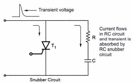
Ques 49. The snubber circuit is used in thyristor circuit for:
Triggering
dv/dt Protection✓
di/dt protection
Phase-shifting
The transient overvoltages can switch on the thyristor. In some cases, the thyristor can be damaged due to these transient voltages. These transient voltages are very common when the converter is having inductive loads.
Snubber circuit: The thyristors can be protected against transient voltages by an RC network This RC network is connected in parallel across the thyristor. It is called a snubber circuit.
Fig. shows a snubber (RC) circuit. The resistance has a value of a few hundred ohms. Whenever there is a large spike or voltage transient across the thyristor, it is absorbed by the RC circuit.
The RC circuit (snubber) acts as a lowpass filter for this voltage transient. A low-pass filter (LPF) is a filter that passes signals with a frequency lower than a certain cutoff frequency and attenuates signals with frequencies higher than the cutoff frequency.
The resistance has a normally low value so that the transient is absorbed by the capacitor quickly. Thus the thyristor is protected against voltage transients. The RC snubber circuit is very commonly used for the protection of thyristors against transient voltage High-frequency voltage spikes).
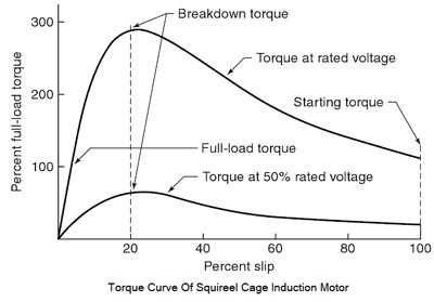
Ques 50. Starting torque of a three-phase squirrel cage induction motor at rated voltage is:
30% to 40% of the rated torque
The rated torque
100% to 200% of the rated torque✓
5 to 7 times of the rated torque
Consider that basically, an induction motor at standstill is a transformer, with an essentially shorted secondary. When power is applied to the stator, a voltage is induced into the rotor, which, being shorted develops the current which creates the magnetic field to pull the rotor along with the stator’s rotating field.
Since a large amount of current flows through both the stator and rotor, a strong magnetic field is established in both the stator and rotor.
The starting torque of a squirrel-cage motor is high since the magnetic field of both the stator and rotor are strong at this point. The starting torque of a typical squirrel-cage motor can range from 200% to 300% of its full-load rater torque.
Although the starting torque is high, the squirrel-cage motor does not develop as much starting torque per ampere of starting current as other types of three-phase motors.
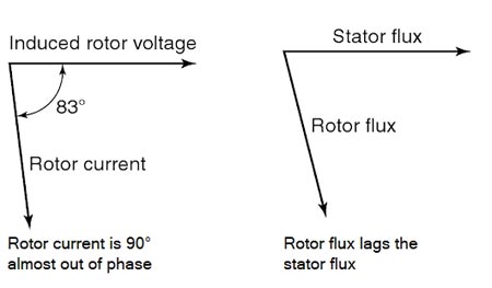
As we know that the torque developed by an induction motor is the difference in phase angle between stator flux and rotor flux.
Since the rotor is being cut at a high rate of speed by the rotating stator field, the bars in the squirrel-cage rotor appear to be very inductive at this point because of the high frequency of the induced voltage.
This causes the phase angle difference between the induced voltage in the rotor and rotor current to be almost 90° out of phase with each other, Producing a lagging power factor for the rotor This causes the rotor flux to lag the stator flux by a large amount, and consequently a relatively weak starting torque per ampere of starting current, compared to other types of three-phase motors, is developed.
Maximum torque is developed when the stator and rooter flux are in phase with each other.
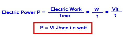
Ques 51. Which of the following is not the same as watt?
Joule/sec
Ampere2 × ohm
Volt2 × ohm
Volt/Ampere✓
The rate at which the electric work is done in an electric circuit is called electric power. The SI unit of power is joule per second or watt.
Now Since Power = I2 x R = Ampere2 x ohm
P = V2/R = Volt2 x ohm
Note:- Volt Per Ampere (V/A) is a unit in the category of Electric resistance. It is also known as volts/ampere, volts/amp.
Ques 52. One millivolt will be equal to:
0.01 V
0.001 V✓
0.0001 V
0.1 V
1 milli-Volt ampere is equal to 10-3 volt which is equal to 0.001 V
Ques 53. Which of the following 1-phase induction motor has the highest starting torque?
Split-Phase
Capacitor-Start✓
Capacitor-Run
Capacitor-Start, Capacitor-Run
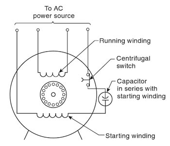
The capacitor-start motor is essentially the same as a split-phase motor where the two windings are out of phase with each other, providing the necessary, Starting torque for starting the motor to rotate. The capacitor is added in series with the starting winding.
The purpose of the capacitor is to produce a larger phase shift and a resultant starting torque that is substantially higher than that of any other single-phase induction motor. When the motor reaches 70 to 80 percent of full speed about three seconds after it begins to turn, the centrifugal switch opens. This disconnects both the start winding and the capacitor from the circuit.
During start-up with a capacitor-start motor, the reactance of the capacitor cancels the inductive reactance of the start winding. This effect allows a high surge current for a brief period of time, causing a large magnetic field to form around the starting coil.
The auxiliary coil of a capacitor-start motor has a greater number of turns than the auxiliary coil of a resistance-start motor. Therefore, its coil has a greater number of ampere-turns, which produces a larger rotating flux and a stronger starting torque. Despite having a larger inductive reactance due to more coil turns, the phase shift is kept close to 0 degrees because XC and XL cancel each other.
The capacitor causes the start-winding current to lead to the applied voltage. Because the run-winding current lags the applied voltage by nearly 90 degrees, as shown in Figure.
A capacitor-start motor has a starting torque that ranges from 225 to 400 percent its rated full-load running torque.
Ques 54. For the grounding of an entire sub-station:
Counterpoise are used
Grounding Rods are used
Grounding Mats are used✓
Peterson coil is used
A substation is an assembly of a large no of electrical equipment. All the equipment, as well as working personnel, must be safe even in adverse conditions.
The substation grounding system is an essential part of the overall electrical system. The proper grounding of a substation is important for the following two reasons:
1. It provides a means of dissipating electric current into the earth without exceeding the operating limits of the equipment.
2. It provides a safe environment to protect personnel in the vicinity of grounded facilities from the dangers of electric shock under fault conditions.
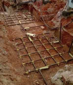
The grounding system includes all of the interconnected grounding facilities in the substation area including the ground grid, overhead ground wires, neutral conductors, underground cables, foundations, deep well, etc. The ground grid consists of horizontal interconnected bare conductors (mat) and ground rods. The design of the ground grid to control voltage levels to safe values should consider the total grounding system to provide a safe system at an economical cost.
There are some standards that guide the grounding of the substation.
As per IEEE standards, earth mats are designed with vertical ground rods, and earth mats bring down the overall resistance of the substation below 1 Ohm. The Earth mat spreads across the substation. All the equipment is connected to the earth mat with two separate earth flats.
A good grounding scheme will ensure faster fault clearing and a low enclosure potential rise.
A counterpoise is a galvanized steel wire which either runs in parallel, radial, or a combination of two, with respect to the overhead transmission line.
Grounding rods are mainly used for the protection of homes and industries under abnormal conditions.
Peterson coil is an iron core reactor connected between transformer neutral and ground. It is used for limiting the capacitance earth fault current which is flowing when the line ground fault occurs in the line.