Ques 65. In a balance 3-φ supply system, the vector sum of the three-phase EMFs at any instant is equal to:
Phase voltage
Line voltage
Zero✓
Maximum value
A balanced three-phase voltage supply consists of three individual sinusoidal voltages that are all equal in magnitude and frequency but are out-of-phase with each other by exactly 120o electrical degrees. The phase voltages are all equal in magnitude but only differ in their phase angle. The three windings of the coils are connected together at points, a1, b1 and c1
Then Red phase VRN = Vm sinθ Yellow Phase VYN = Vm sin(θ – 120°) Blue Phase VBN = Vm sin(θ – 240°) or VBN = Vm sin (θ + 240°)
If the red phase voltage, VRN is taken as the reference voltage so the voltage in the yellow phase lags VRN by 120°, and the voltage in the blue phase lags VYN also by 120°. But we can also say the blue phase voltage, VBN leads the red phase voltage, VRN by 120°.
As the three individual sinusoidal voltages have a fixed relationship between each other of 120o they are said to be “balanced” therefore, is a set of balanced three-phase voltages their phasor sum will always be zero as Va + Vb + Vc = 0
Ques 66. The iron losses in a 100 kVA transformer are 1 kW and the full load copper losses are 2 kW, the maximum efficiency occurs at a load of:
Ques 67. The ratio of voltage and current in a closed circuit
Varies
Remain Constant✓
Increases
Decreases
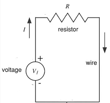
Electrical current is usually Carried in the thin wire and generally returns to where it started to form a circuit. We can draw a simplified picture of an electrical circuit, using line segments for wires, a circle to symbolize a voltage source (like a battery or generator), and a resistor. This is known as a schematic diagram or just a schematic for short.
The schematic for a simple circuit containing only a resistor and a voltage source is shown in Figure. The figure also shows a ground symbol. The voltage along a wire is constant. The voltage source creates a voltage difference V, between the top and bottom connections.
By Ohm’s law the current that flows through the resistor is the ratio of voltage to resistance:
I = V/R
The current is constant all around the circuit because there’s nowhere else for it to go (assuming the electrons are all stuck on the wire): this statement can be formalized as one of Kirchhoff’s laws.
By Ohm’s law
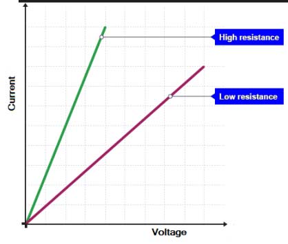
Ohm’s law of constant proportionality states that for a given conductor the ratio of voltage to current is constant i.e if the temperature, area, the length did not change the resulting current is directly proportional to the variation in the applied voltage. Hence the graph between voltage and current is linear. R(constant) = V/I
★Ohms law does not apply to all material it only applied to “linear” or “Ohmic Resistor”.
Ques 68. The unit of force in the M.K.S system is:
Joules
Newton✓
Kilogram
Newton M
In the SI system, Newton (N) is defined as the force necessary to accelerate one gram mass at 1 m/s2. The engineer’s unit of force in the MKS system is Kilogram-force (kgf). The kilogram force is the force necessary to accelerate 1 kg mass at 9.81 m/s2.
In the SI system, the unit of force has been named Newton (N) in honor of the scientist Newton. 1N is equal to 1 (kg.m)/s2.
Ques 69. What is the name of the instrument used to measure the specific gravity of a battery?
Pyrometer
Hydrometer✓
Lactometer
Fuel Gauge
A hydrometer is used to measure the specific gravity of the electrolyte solution in each cell.
Lactometer is used to measure the purity of the Milk
A pyrometer is a type of remote-sensing thermometer used to measure the temperature of a surface.
Ques 70. What is the unit of torque of a DC Motor in SI unit?
Kilogram-Meter
Newton-centimeter
Joule✓
Newton Per meter
The SI unit of torque is a Newton-metre, which is also a way of expressing a Joule (the unit for energy).The SI unit for energy or work is the joule. It is dimensionally equivalent to a force of one newton acting over a distance of one meter, but it is not used for torque.
Ques 71. Fleming’s left-hand rule is applicable to:
Motor✓
Generator
Transformer
Rectifier
Left-hand rules apply when a current causes Motion and the right-hand rules apply when motion causes current
DC motor uses electrical energy( can use fuel oil eg diesel) to operate and convert it into mechanical energy. This is old and simple technology where Fleming’s left-hand rule works.
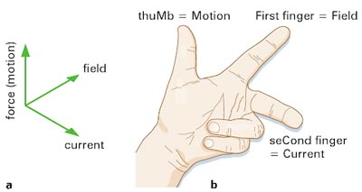
Fleming’s left-hand rule In Figure. there are three things with the direction (three vector quantities –
· the magnetic field
· the current
· the force.
The magnetic field is vertical. The current and the force are horizontal, and at right angles to each other. Hence we have three things that are all mutually at right angles to each other. To remember how they are arranged, physicists use Flamingo’s left-hand rule. It is worth practicing holding your thumb and first two fingers at right angles.
The left hand is held with the thumb, first finger and second finger mutually perpendicular to each other than
The thumb is pointed in the direction of the motion of the conductor relative to the magnetic field i.e direction of the force.
The forefinger is pointed in the direction of the magnetic field.
The middle finger represents the direction of the induced or generated current within the conductor.
We use Fleming’s left-hand rule to predict the direction of the force on a current-carrying conductor in a magnetic field. By keeping your thumb and fingers rigidly at right angles to each other, you can show that reversing the direction of the current or field reverses the direction of the force.
Ques 72. If current i(t) = (5√2 sin100πt + 3√2 sin200πt) flows through a resistance of 2Ω, then the average power absorbed by the resistance is:
Ques 73. The reverse resistance of a diode is of the order of:
K. Ohm’s
Ohm’s
Mega Ohm’s✓
Micro Ohm’s
There will be no current in the circuit as the diode is reverse biased and the diode is reversed biased offering infinite resistance.
In the ideal case diode resistance in forward biased acts as the perfect conductor and in reverse biased, it will act as the perfect insulator.
Ques 74. Which of the following device has the smallest turn-off time?
Thyristor
GTO-Thyristor
MOSFET✓
IGBT
MOSFET is a voltage-controlled majority carrier (or unipolar) three-terminal device. MOSFET switching speed is very fast.
MOSFET has the lowest switching-off time in the order of nanoseconds.
BJT has the turn-off time in the order of nanoseconds to microseconds.
IGBT has the turn-off time in the order of microseconds (about 1 μs).
Thyristor (SCR) has the turn-off time in the order of microseconds (about 5 μs).
Therefore, the increasing order of turn-off times is:
MOSFET > BJT > IGBT > Thyristor (SCR)
Ques 75. In trickle charging, the batteries are given a charge at a very low rate for a long period of time or continuously throughout their service. Trickle charging is used for acid batteries that are stored for relatively long periods.
60°
120°✓
90°
180°
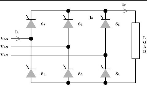
Consider a full-bridge converter consist of RLE Load as shown in fig
Where T1, T3, T5 are positive Group and T4, T6, T2 is of the negative group and the firing angle be 60°. Thyristor must be triggered in the sequence of T1, T2, T3, T4, T5, T6,
Now let us suppose for the first 60 degrees the thyristor T1 and Thyristor T2 from the negative group is conducting after 120° T3 triggered and thyristor T1 is commuted. As soon as T1 triggered the conducting pairs are T2 and T3 hence the thyristor T2 conduct for 60 + 60 = 120. Similarly, all the Thyristor will conduct for 120 degree.