
Ques 91. If the current in the armature of d.c series motor is reduced to 5%, the torque of the motor will become:
- 50% of the Previous Value
- 25% of the Previous Value
- 150% of the Previous Value
- 100% of the Previous Value
Answer. 2. 25%of the previous value In DC series Motor, the torque is directly proportional to the square of the armature current T ∝ Ia2 So if the armature current is reduced to 5% then torque is T = 52 T = 25%
Ques 92. The series field of long shunt compound generator is excited by
- Supply current
- Field current
- Load current
- Armature current
Answer.3. Load Current Explanation:- Voltage regulation of the series generator is very poor but the ability to produce additional useful magnetism in response to increased load is very good. This useful characteristic of the DC series generator and constant voltage characteristic of the shunt generator are combined in the compound generator. As we know that the terminal voltage of the DC generator decreases as the load on the generator is increased. The compound generator was developed to eliminate this problem. In some applications this drop is admissible but in case of lighting loads, it presents a serious problem. For example, in ships, the same generator is used to supply the power to DC machinery as well as to the lighting circuits. So, when the load increases, the terminal voltage decreases. Hence. depending on the load, the generator continually fluctuates. These variations in current produce corresponding changes in the generator terminal voltage, resulting in the flickering of light. A compound generator eliminates this problem. In a compound wound generator, there are two sets of field windings on each pole one is in series and the other is in parallel with the armature. There art two types of compound generators: Short-shunt compound generator in which only shunt field winding is connected in parallel with the armature, as shown in Fig. In short shunt connection series field carries no current at no-load and thus its open-circuit characteristics are same as that of a shunt generator. The current relations of the short-shunt connection of a d.c. compound generator is la = If + IL Where Ia = Armature current Long-shunt compound generator in which the shunt field is connected in parallel will both the series winding and the armature, as shown in Fig. In long shunt connection, the series field winding carries the current same as that of shunt field winding at no-load. The current relations of the long-shunt connection of a d.c. compound generator is la = If + IL Two fields of the compound generators may be cumulative or differential wound. If it is cumulative the two fields are additive and the two fields are subtractive if it is differential wound. The essential difference between the two is that in the short-shunt connection, the armature current excites the series field, whereas, in the long-shunt connection, the load current excites the series field.Compound Generator

If = Field current
IL = Load current
Ques 93. In the method of speed control of an induction motor by inducing EMF in the rotor circuit, if the injected voltage is in the phase opposition to the induced rotor EMF, then
- The rotor resistance Increase
- The rotor reactance increase
- The rotor reactance decrease
- The rotor resistance decrease
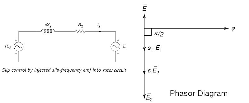
Answer.1. The rotor resistance Increase Explanation:- Speed control of Induction motor by injecting SLip Frequency E.M.F. into Rotor Circuit In this method, a voltage is injected into the rotor circuit. The frequency of rotor circuit is a slip frequency and hence the voltage to be injected must be at a slip frequency. It is possible that the injected voltage may oppose the rotor-induced e.m f. or may assist the rotor-induced e.m.f. Since the speed of the rotating magnetic field in the space is equal to the slip sliced, the emf induced to the secondary (stator) also corresponds to the slip frequency. The voltage injected into the stator winding will always be at the slip frequency when the brushes are connected to the stator windings. It is possible to adjust the phase of the voltage injected into the secondary winding, that is, the stator either in-phase or antiphase (out of phase) with the stator-induced voltage. The figure shows the phasor diagram of the emf injected into the secondary. Let us consider the following: E2, be the magnitude of standstill secondary voltage, s be the no-load slip at the motor, E be the magnitude of the voltage injected into the motor secondary and s1 be the new operating slip after injecting the voltage. If the injected voltage is in phase opposition to E2, the resultant voltage in the rotor circuit become s1E2 − E. as shown in fig. We have the following expression for the new slip s1 Initially, the speed cannot change due to the inertia of the rotor, the net emf in the rotor circuit reduces to a value (s1E2 − E), as a result of which the rotor current I, and, hence, the torque developed decreases. But, since the load “torque remains constant, the speed of the motor starts decreasing. This process of reduction in speed (increase in slip and resistance) continues till the rotor induced emf increases to circulate enough current in the rotor to develop the desired torque. sE2 = s1E2 − E s1E2 = sE2 + E or s1 = s + E/E2 i.e. when the emf injected is in phase opposition to the rotor induced emf, the slip increases or the speed of the motor decreases. By similar reasoning, it is easy to observe that when the injected emf is in phase with the rotor induced emf, the slip and resistance decreases or the speed of the motor increases. Eqn., under such conditions, will be expressed as s1 = s + E/E2 Thus by controlling the magnitude of the injected e.m.f., rotor resistance and effectively speed can be controlled. Practically two methods are available which use this principle. These methods are, 1. Kramer system 2. Scherbius system
Ques 94. In the method of synchronization of an alternator to the bus-bar, a Synchroscope indicate correct speed when
- The pointer moves towards Left
- The pointer moves towards Right
- The pointers move vertically up
- The pointers vibrate at the center
Answer.3. The Pointer move vertically up Explanation:- A synchroscope is a device that produces a revolving field proportional to the speed difference between the incoming machine and the system. It is constructed so that the angular phase difference is indicated on the synchroscope dial. or A synchroscope indicates when two AC generators are in the correct phase relation fo connecting in parallel and shows whether the incoming generator is running faster or slower than the on-line generator. The synchroscope measures the difference in voltage and frequency of the two alternators. The pointer of the synchroscope is free to rotate in a 360° arc. The alternator already connected to the load is considered to be the base machine. The synchroscope indicates whether the frequency of the alternator to be parallel to the base machine is fast or slow. When the voltages of the two alternators are in phase, the pointer covers the shaded area on the face of the meter. When the two alternators are synchronized, the synchronizing switch is closed. The voltage from one phase of the three-phase bus bar system is connected to one set of synchroscope coils. The voltage from the same phase of the incoming alternator is connected to another set of synchroscope coils. A pointer is attached to the synchroscope rotor and rotates over a dial face.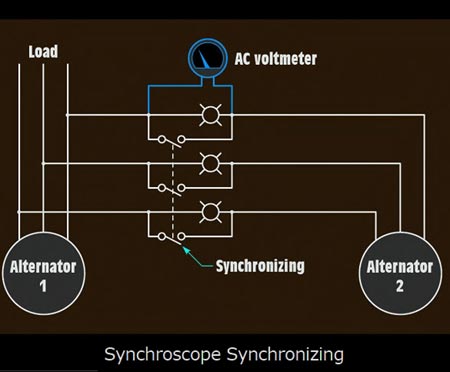
Ques 95. Which of the following motors can be used as the part of the control circuit in the robotic application?
- AC series Motor
- Universal Motor
- Servo Motor
- Scharge Motor
Answer.3. Servo Motor Explanation:- A servomotor is a rotary actuator or linear actuator that allows for precise control of angular or linear position, velocity, and acceleration. It consists of a suitable motor coupled to a sensor for position feedback. It also requires a relatively sophisticated controller, often a dedicated module designed specifically for use with servomotors. Servo motors are motors combined with a sensor so that the position/velocity/torque of the motor at a given instance can be measured and corrected using the fundamentals of control systems.
In servomotors, the desired value of position/velocity/torque is provided as an input and the actual value of the same is taken as the output. The voltage/current is varied in such a way that the difference between the output and input is minimized. The device which varies the voltage/current of the motor is called as the controller of the motor. One of the most famous and widely used controllers are PID controllers.
Now, that we are clear about what servomotors are we can see why they are preferred in robots.
Robots are designed in such a way that they are able to perform a wide variety of tasks. Move from one point to another at different speeds. Pick objects from any random point and place it at any other point. So, while doing this the speed and position of the must be precisely controlled. This can be achieved using servo motors.
There are other popular motors types, that are used in robots, stepper motors are one example. However, due to torque and speed considerations servo motors are preferred.
Ques 96. During the starting of a slip ring induction motor using rotor resistance starter, the insertion of resistance in the rotor circuit causes:
- Stator current to Increase and torque to decrease
- Stator current to decrease and torque to increase
- Stators current to Increase and power factor to decrease
- Power factor to decrease and torque to Increase
Answer.2. Stator current to decrease and torque to increase Explanation:- This type of starter is used with a slip-ring wound rotor motor. These motors and starters are primarily used where the motor will start against the full load, as an external resistance is connected to the rotor windings through slip rings and brushes, which serves to increase the starting torque. Since the starting torque per phase of the induction motor is directly proportional to the rotor winding resistance and terminal voltage. Therefore, the addition of a resistance in the rotor circuit not only reduces the current drawn by the motor but also increases the starting torque. By adding a suitable external resistance in the rotor circuit, such that r2‘ = x2‘, the starting torque can be made equal to the maximum torque developed. This is an ideal method used for starting slip-ring induction motors on load. This facility by which the starting torque can be varied in a slip-ring induction motor is the main advantage of this type of motors over the squirrel-cage type motors. The figure shows the wiring diagram of the rotor resistance starter. The motor is started by closing the triple pole supply switch. Then, when the arm A is rotated in the clockwise direction, the motor starts. When the motor is first switched on, the external rotor resistance is at a maximum. As the motor speed increases, the resistance is reduced until at full speed, When it has reached the full rated speed, then the arm is moved to the ON position such that the external resistant gets completely cut off. Now the external resistance is completely eliminated and the machine runs as a squirrel-cage induction motor. This method is generally used for the starting of large motors.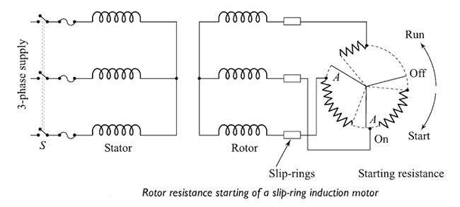
Ques 97. In case of an electromechanical generator, the frequency is
- Directly proportional to the voltage
- Indirectly proportional to the speed
- Directly proportional to the speed
- Indirectly proportional to the power
Answer.3. Directly proportional to the speed Explanation:- Electromechanical devices are reluctance motor, Synchronous Motor, Induction Motor etc. A dc generator produces voltage level proportional to the speed while the AC motor produces voltage level proportional to the frequency. The synchronous speed of an alternator is given as Ns = 120f/P Where f = frequency Large electric power grids are complex dynamical systems, displaying electromechanical coupling on a nearly continental scale. Electrical frequencies are among the key output variables reflecting electromechanical behavior. At locations with synchronous generation attached, the inherent physics of the synchronous machine dictate that electrical frequency of the generator voltage and mechanical rotational speed of the generator are locked in fixed proportion to each other, so that variation of frequency directly reflects deviations in rotational speed away from the desired steady state.
P = number of poles
Ques 98. A three-phase induction motor is analogous to
- Generator
- Rotating transformer
- Rotating Motor
- Rotating converter
Answer. 2. Rotating Transformer Explanation:- Analysis of transformer model is very easy to visualize then induction motor so, the induction motor is generalized as transformer because of following reasons : Because of the above reasons Induction motor is called a two windings transformer with secondary short-circuited.
Ques 99. In the direct-online starter, NO-VOLT release is to
- Safeguard the motor against the failure of the supply
- Safeguard against earth fault
- Safeguard against Overload
- Safeguard against supply fluctuation
Answer.1. Safeguard the motor against the failure of the supply Explanation:- In the case of small capacity motors having a rating of less than 5 hp. The starting current is not very high and such motors can withstand such starting current without any starter. Thus there is no need to reduce applied voltage, to control the starting current. Such motors use a type of starter which is used to connect stator directly to the supply lines without any reduction in voltage. Hence the &starter is known as the direct online starter. Though this starter does not reduce the applied voltage, it is used because it protects the motor from various severe abnormal conditions like overloading, low voltage, single Chasing etc. The NO contact is normally open and NC is normally closed. At the start, NO is push for fraction of second due to which coil gets energized and attracts the contractor. So stators directly get supply. The additional contact provided ensures that as long as supply is ON, the coil gets supply and keeps contactor in ON position. When NC is pressed, the coil circuit gets opened due to which coil gets de-energized and motor gets switched OFF from the supply. Under overload condition, current drawn by the motor increases due to which there is an excessive heat produced, which increases temperature beyond the limit. Thermal relays go opened due to high temperature, protecting the motor from overload conditions. Hence from the above it clear that No Volt Coil ensures that whenever supply resumes after switching off or supply failure, the motor does not start on its own, but starts only after the user starts it and that too through current limiting resistors. When the supply voltage is below 85% of its rated voltage or it suddenly fails, the no volt-coil becomes demagnetized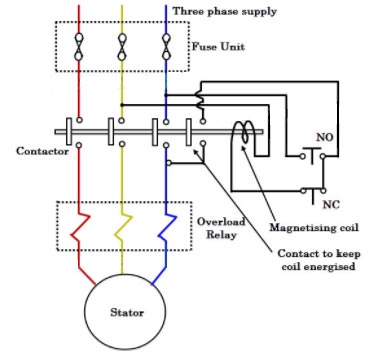
Ques 100. Synchronous Motor for the rotary Kilns Run at
- Ultra high speed
- Ultra Low speed
- Low Speed
- Medium speed
Answer. 2. Ultra Low Speed Explanation:- Synchronous motors have the following advantages as compared to 3-phase induction motors :
FOR TRANSMISSION AND DISTRIBUTION SYSTEM MCQ CLICK HERE
FOR DC MOTOR MCQ CLICK HERE
FOR 3-Φ INDUCTION MOTOR MCQ CLICK HERE
FOR SYNCHRONOUS GENERATOR OR ALTERNATOR MCQ CLICK HERE
