Ques 21. Under which of the following condition the squirrel cage induction motor is preferred over the wound rotor induction motor.?
- When an external voltage is to be necessarily into the rotor
- When the wide range of speed control is required
- When the cost is the major consideration
- When higher starting torque is required
Answer.3. When the cost is the major consideration Explanation:- In the squirrel cage motor, the bar at both ends is a permanently short circuit by the end rings. Hence the resistance of the squirrel-cage induction motor cannot be varied as compared to the slip ring induction motor. In the squirrel-cage induction motor, the rotor has very low fixed resistance, therefore, the starting torque is low due to low power factor and high reactance. The starting torque could be increased by increasing starting resistance but due to high current in the rotor during starting will increase the copper loss which will decrease the motor efficiency. Advantages of Squirrel cage induction motor Disadvantages of Squirrel cage induction motor
Ques 22. _________ are employed for the operation of Jaw Crushers
- DC shunt wound motor
- Squirrel cage induction motor
- Belted slip ring induction motor
- Any DC motor
Answer.3. Belted slip ring induction motor Explanation:-
Ques 23. A synchronous Motor is found more economical when the load is above
- 1 kW
- 10 kW
- 20 kW
- 100 kW
Answer 4. 100 kW Explanation:- A synchronous motor is electrically identical to an alternator or A.C generator. The synchronous motor speed can be controlled by the varying the frequency of its source. Due to the non-availability of economical variable frequency sources, speed control of this method was not used in past. These motors are mainly used in constant speed applications. Synchronous motor drives are close competitors to induction motor drives in many industrial applications and their application is growing. Synchronous motors are generally more expensive than induction motor drives, but the advantage is that the efficiency is higher, which tends to lower the life cycle cost. The development of semiconductor variable frequency sources, such as inverters and cyclo-converters, has allowed their use in variable-speed applications such as high power and high-speed compressors, blowers, induced and forced draft fans, mainline traction, servo drives, etc. Most synchronous motors are rated between 150 kW and 15 MW and run at speeds ranging from 150 to 1800 rpm. Synchronous motors are made in speeds from 1800 (two-pole) 150 rpm (48-pole). They operate at a constant speed without slip an important characteristic in some applications. Their efficiency is 1-2 to 5% higher than that of induction motors, the higher value at the lower speeds. They are the obvious choice to drive large low-speed reciprocating compressors requiring speeds below 600 rpm. Why do, above 100 kW, synchronous motors predominate over induction motors? Because the reactive power control through excitation is possibly easier with synchronous motors, and thus the requirements in this regard from the full power PECs (power electronic converters) are lower. Consequently, the PECs are simpler and less expensive and the overall costs of the drive are lower, though the synchronous motor, for comparable power and speed, is more expensive than the induction motor. The efficiency of the synchronous motor above 100 kW is also, in general, higher than that of the cage-rotor induction motor. Also, the cost per horsepower is generally higher than that of a 3-phase induction motor. Hence synchronous motors are rarely used below 100 kW. because of their much higher initial cost compared to 3-phase induction motors. However, their unique characteristics of constant-speed operation, power-factor control, and high operating efficiency make them highly suitable for heavy industry, particularly for applications requiring low speed and high horsepower.
Ques 24. When quick speed reversal is is a consideration, the motor preferred is
- Synchronous Motor
- Squirrel cage Induction Motor
- Wound Rotor induction motor
- DC motor
Answer 4. DC Motor Explanation:- There are three different types of DC open loop motors. All DC motors have an armature, field windings, and housing. How the field windings are set up changes the operating characteristics of the motor. The three ways to set up field windings are In a permanent magnet DC motor, permanent magnets line the inside of the motor housing. The armature is made from a hunk of iron wrapped in multiple turns of copper wire. In series and shunt wound motors, the field windings are electromagnets, wired to the same power source as the armature. Each of the three methods of DC motor winding has its advantages and disadvantages. In general, permanent magnet and shunt motors are more easily adapted to use as the main drive motors for a robot that are series wound motors. The problem with series wound motors is that they are harder to reverse. While permanent magnet and shunt wound motors can be easily reversed by simply switching the direction of the armature current, a series wound motor must be completely rewired in order to enable the motor to reverse. Permanent magnet DC motors The small DC motors (which has 12V or below 12V) made up of a permanent magnet i.e. it contains the permanent magnetic field. If you want to change the direction of the shaft you change the polarity only. Because it contains only armature winding only. Temporary magnet DC motors The high voltage DC motors (which has 220V or above 220V) made up of temporary magnet i.e. field and armature have separate winding. So if you change the polarity of the supply the total circuit will change. Due to that, the motor will rotate in the normal direction. If you want to change the direction of the shaft you need to change either field or armature supply. Take care, that you change either the field or the armature wires. If both are changed at the same time, the direction remains same. For a brushless DC motor, reversing the supply polarity won’t work and will possibly damage the motor. The electronic commutation needs to be reversible, which has to be part of the motor design. In case of single phase AC motor the direction can be changed by changing the wiring in the starting circuit In case of three phase induction motor, the direction of rotation can be changed by changing any two of the phases. The direction of rotation of the synchronous motor is determined by its starting direction, as initiated by induction motor action. Thus, to reverse the direction of a 3 phase synchronous motor, it is necessary to first stop the motor and then reverse the phase sequence of the 3 phase connections at the stator. REVERSING THE CURRENT TO FIELD WINDINGS WILL NOT AFFECT THE DIRECTION OF ROTATION. Hence from the above discussion, it is clear that for quick speed reversal the dc motor is more suitable than any other type of motor.
Ques 25. Stator voltage control for the speed control of induction motor is suitable for
- Fan and Pump Drive
- Drive of a crane
- Running as the generator
- Constant Load drive
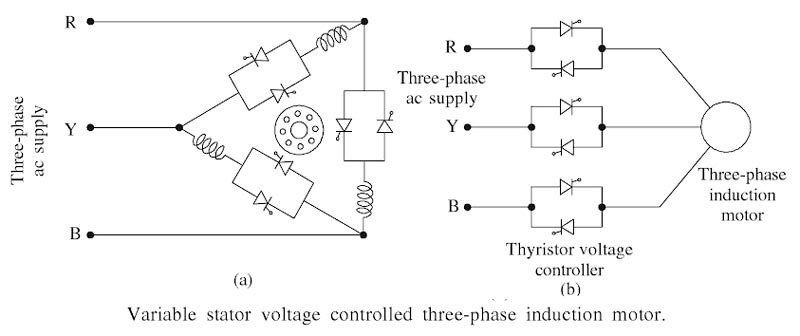
Answer 1. Fan and Pump Drive Explanation:- Generally, the drives used in industrial applications are classified into two types, viz., constant speed drives and variable speed drives. For constant speed applications, A.C machines are used. Because of the speed controls, conventional methods for ac machines are either expensive or highly inefficient. For variable-speed applications, dc machines are preferred. DC drives have been extensively used in the industry for variable speed applications for a long time, but gradually ac drives have been introduced into this field. This is due to the fact that cage-type induction motors have several advantages over dc machines, and the speed of the induction motor can be controlled by controlling either its rotor frequency or stator frequency. Generally, the following methods are used for speed control of the induction motors. A few methods depend on the change of supply frequency and the number of poles. These methods include Amongst these methods, only those that make use of static power converters in one form or another are The torque developed by an induction motor is proportional to the square of the terminal voltage (T ∝ V2) at a constant value of the supply frequency and the slip. When the applied voltage is varied, a set of speed-torque curves can be obtained. Stator voltage control for three-phase induction motors of both slip ring as well as squirrel cage type can be implemented by using three-phase ac voltage controllers. The figure shows two commonly used symmetrical three-phase ac voltage controller circuits for delta and star-connected stators. For small size motors, TRIACs may be used. The effective load voltage in three-phase ac circuits can be varied by a thyristor controller consisting of a pair of antiparallel thyristors in a delta-connection as shown in Fig. (a) and in star-connection shown in Fig. (b). Each pair of back-to-back thyristors controls the voltage delivered to one phase of the stator, and the phase voltage waveform consists of a series of sine-wave segments. A phase displacement of 120° is maintained between the sets of gating pulses delivered to each controller in order to produce a symmetrical reduction of the three-phase voltages. In the full voltage condition, each thyristor receives a gating signal at the start of the positive half cycle of its anode to cathode voltage. The series thyristor pair is then virtually a short-circuit and the stator phase receives a complete cycle of the supply voltage. As the thyristor firing is delayed, the conduction period of each thyristor is shortened and the effective stator voltage is reduced. When the firing delay is 180°, the thyristor controller is open-circuited and the motor voltage and current are both zero. Speed control is obtained by varying conduction period of thyristors. For motors with low power ratings, the anti-parallel thyristor pair can be replaced by a TRIAC. The ac voltage controllers are also used for a soft starting of motors. It is well known that the torque developed in an induction motor at a given slip varies approximately with the square of the stator voltage. The steady state operation occurs when load torque is balanced by the motor torque. Thus, the rotor speed can be varied smoothly by varying the stator voltage without changing the supply frequency. The direction of rotation of the three-phase induction motor can be reversed by changing the phase sequence of the stator voltages by introducing two additional thyristor controllers. The merits and demerits of this method of stator voltage control can be enumerated as follows: Advantages of Stator voltage control Disadvantages of Stator voltage control Application:- Due to its high loss and low efficiency, this method found application when the load is predictable and where the load torque is relatively low at the reduced speed (fan type load). e.g pumps, fans, blower drive.
AC voltage control or the stator voltage control
Ques 26. The selection of control gear for a particular application is based on the consideration of
- Duty
- Starting Torque
- Limitation of starting current
- All of the above
Answer D. All of the above Explanation:- Motor Selection The range of electric motor applications is so broad that it is difficult to establish precise rules for motor selection. The differences between applications such as whit traction, robot motion, micromotors, disk drives, manufacturing machines, and pun systems, for example, are so many that it is virtually impossible to specify what t best motor would be, unless the application and its environment were clearly specific The aim of this subsection is simply to outline a procedure that can help in narrowing down the choice of a suitable drive motor to a few most likely candidates. The first step in selecting a motor is the analysis of the requirements impost by the application; these can be divided into three groups: The table given below summarizes the important considerations for each of these. On the basis of the requirements listed in Table, one can undertake the task of selecting a motor for a specific application. [ninja_tables id=”28041″] Selection of Electric Motor for any application The selection of an electric motor for any application depends on the following factors: For a particular application, the type of electric drive and control gear determines by the following considerations:
Ques 27. As compared to three phase induction motor the advantage of synchronous Motor in addition to its constant speed is
- Higher Power factor
- Better efficiency
- Both 1 & 2
- None of the above
Answer.3. Both 1 & 2 Explanation:- Synchronous motors have the following advantages as compared to 3-phase induction motors:
Ques 28. In motor, the static frequency changers are used for
- Power factor management
- Improved cooling
- Reversal of direction
- Speed Regulation
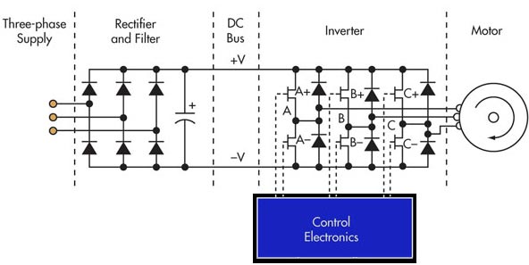
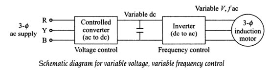
Answer 4. Speed Regulation Explanation:- An ac motor can also be used as a drive motor. Among the motors used are induction motors and synchronous motors. Both slip ring and squirrel cage induction motors are used. The squirrel cage motor has advantages overslip ring one in that it is robust and has a simple construction. When compared to a dc motor it has a large power/weight ratio. An ac motor is normally a constant speed machine and its speed control over a wide range in a smooth and step-less manner had been a problem. It is well known that the speed of an ac motor can be varied if the supply frequency can be varied. The speed control can be smooth if a continuously variable frequency supply is available. Rotating machines have been used to provide a variable frequency supply. Similar to the conventional Ward-Leonard system for dc motor, an MG (Motor- Generator) set is used here to provide variable frequency supply. The system has the disadvantage of high initial cost, poor efficiency and it occupies plenty of space. But the advent of thyristors and thyristor power converters has paved the way for static frequency conversion. The ability to achieve a voltage or current of controllable frequency using thyristors presents the possibility of a variable speed drive using an ac motor. The static frequency conversion has several advantages over rotating frequency conversion equipment. The ac motor can have precise speed control. However, when the supply frequency is varied, the voltage applied to the motor should also be simultaneously varied to avoid saturation. Static frequency conversion equipment can be controlled to, provide a variable voltage supply, and the advantage being that they can be independently varied. The ac motor is operated at constant flux at every operating frequency. Static frequency converter is a device which alters the frequency of input signal according to the input set point. As the name specifies, it consists of solid-state switching devices which are either on or off according to the input control signal. The following figure shows the essential elements of a static frequency converter. The 3-phase supply is rectified and filtered to produce a DC bus, which powers the inverter section of the static frequency converter. The inverter consists of three pairs of semiconductor switches (MOSFET, GTO, power transistor, IGBT, etc.) with associated diodes. Each pair of switches provides the power output for one phase of the motor. Each pair of semiconductor switches is driven by the control electronics to generate a high-frequency square wave carrier pulse waveform at each of the phase outputs. Since the carrier is identical on all three phases, the net voltage appearing across any phase of the motor windings due to the carrier alone is zero. In order to drive the motor, the control electronics generate three low-frequency sine waves, 120 degrees apart, which modulate the carrier pulses to each pair of switches. The width of the positive and negative pulse within each carrier cycle is modulated according to the amplitude of the low-frequency sine waveform of that phase. As a result, the average voltage presented to the motor winding is approximately sinusoidal. The two other phases of the motor winding have similar average voltages spaced 120 degrees apart. As static frequency converters operate with an output frequency from a few Hz up to about 100 Hz, they use a carrier frequency in the range of 2 kHz up to about 10 kHz. As power semiconductors improve, the trend is to increase carrier frequencies up to ultrasonic frequencies (> 18 kHz), which can lower losses in the motor since the current is more sinusoidal. The downside is higher switching losses in the inverter and potential for more radiated frequency noise. The are three basic types of Static converters as follows: The static frequency conversion is achieved using single stage conversion devices like cyclo- converters or two-stage conversion devices like dc link converters. Using a cyclo-converter, a very good quality low-speed drive can be obtained having inherent regeneration and reverse rotation possibilities. A dc link inverter uses two stages for frequency conversion. The ac is first rectified to dc which is inverted back to ac of desired frequency. The voltage control of the inverter is obtained externally by the control of firing angle of the rectifier. Sometimes certain advantages are achieved by controlling the voltage in the inverter itself. In these cases, the inverters are voltage source inverters (VSI). The advantages of static frequency conversion devices are as follows:Static Frequency Converter
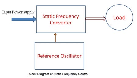
Types of static Frequency converters
Ques 29. V/f is maintained constant in the following case of speed control of induction motor:
- Below base speed with voltage control
- Below the base speed with frequency control✓
- Above base speed with frequency control
- None of these
Answer 2. Below the base speed with frequency control Explanation:- An induction motor on a normal supply operates with a rotating field set up by three-phase currents in the stator winding. The magnitude of the field is controlled broadly by the voltage impressed upon the winding by the supply. This is because the resistance of the winding results in only a small voltage drop, even at full-load current, and therefore in the steady state the supply voltage must be balanced by the e.m.f. induced by the rotating field. This e.m.f. depends on the product of three factors: Synchronous speed, therefore, the motor speed can be controlled by varying supply frequency. The voltage induced in the stator is proportional to the product of supply frequency and air-gap flux. If V = φF And also the torque of an induction motor is directly proportional to the flux T ∝ φ ∝ V/F Hence for the same design parameters [φ remaining the same] and ratio V/F, the torque of the motor, T, will remain constant. Since both V and f, are functions of the supply system, a variation in V and f can alter the performance and the speed-torque characteristics of a motor as required, at constant torque. Increased Voltage If in the steady state, the voltage applied to the stator terminals is increased without a corresponding increase in the frequency, only the flux can vary to regain the balance between applied voltage and e.m.f. If the flux is forced to increase by applying excessive voltages, the iron core of the machine is driven progressively into saturation. This not only increases iron losses due to hysteresis and eddy currents but can lead to a very marked increase in stator current, with corresponding resistive losses. Since most machines are designed to work with the minimum of material, their magnetic circuits are normally very close to saturation and excessive stator voltage is a condition which must be carefully avoided. Reduce frequency Any reduction in the supply frequency, without a change in the terminal voltage, causes u increase in the air-gap flux. Induction motors are designed to operate at the Knee point of the magnetization characteristic to make full use of the magnetic material. Therefore, the increase in flux will saturate the motor. This will increase the magnetizing current, distort the line current and voltage, increase the core loss and the stator copper low, and produce a high-pitch acoustic noise. Base Speed Base speed,” is defined as the speed at which the motor will first produce its maximum designed power output, and “maximum speed,” the fastest the motor can spin while producing that same amount of power (available torque falls off as speed increases past “base speed.”) Operation above base speed First, operation above base speed is easily achieved by increasing the output frequency above the normal mains frequency since the rise in the applied voltage which is not permissible beyond the rated voltage, and which has already been attained by reaching the rated speed. The speed beyond the rated is therefore obtained by raising the supply frequency alone and maintaining the voltage at constant as it rated value. Since V is constant above base speed, the flux will fall as the frequency is increased after the output voltage limit is reached. The machine flux falls in direct proportion to the actual V/f ratio. Although this greatly reduces the core losses, the ability of the machine to produce torque is impaired and the less mechanical load is needed to draw full-load current from the inverter. The drive is said to have a constant power characteristic above base speed. Many applications not requiring full torque at high speeds can make use of this extended speed range. Operation below base speed Each AC induction motor is designed to run at a particular RPM, called base speed. When power is applied, the motor accelerates from 0 RPM. As it does, the torque remains constant and the horsepower increases until the base speed is reached, . Above base speed, the torque falls off while the horsepower remains constant. Below the base speed (V/F ratio is maintained constant, except at low frequencies where (V/f ) ratio is increased to keep maximum torque constant. By maintaining a constant ratio of voltage to speed, we can maintain a constant air gap flux. Because torque is proportional to air gap flux, hence by constant V/f ratio, the torque can be made independent of speed in an AC motor. Hence we can achieve constant torque down to very low speeds. Example One example is a paper winder. When it begins to wind, the empty core is light and does not require much torque to turn. Therefore, it can be turned above base speed at a reduced torque. As the roll is being wound and becomes heavier, the torque required to turn it becomes greater. Therefore, it is necessary for the drive to slow the speed and eventually run below the base speed so that torque is increased to handle the load. Eventually, the roll is heavy and requires the motor to provide maximum torque.
stator drop is neglected, terminal voltage can be considered proportional to the product of
frequency and flux.
and φ = V/F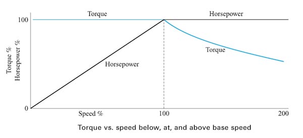
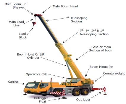
Ques 30. In case of traveling cranes, the motor preferred for boom hoist
- AC Slip Ring Motor
- Ward Leonard Controlled DC Shunt Motor
- Synchronous Motor
- Single Phase Motor
Answer.1. AC Slip Ring Motor Explanation:- A hoist having a spar projecting from the mast to support and guide the load is called Boom Hoist. For crane travel, trolley travel and boom hoist of traveling crane require high starting torque and constant speed in operation. Hence slip ring induction motor is preferred. In SLIP RING induction motor the ends of the rotor windings are externally connected by a variable rheostat (resistance is varied in order to give it proper starting and running current). So more the resistance, more the torque. When we add resistance to the rotor the torque is high, the slip is high and the current is reduced. With the correct value of (usually) resistance inserted in the rotor circuit, a near-unity relationship between torque and supply current at start can be achieved, such as 100%full load torque (FLT), with 100% full load current (FLC) and 200% FLT with 200 percent FLC. This is comparable with the starting capability of the dc machine. Not only high starting efficiency but also smoothly controlled acceleration historically gave the slip ring motor a great popularity for lift, hoist and crane applications.