1. Induction type instruments are used for _______
A.C. measurements
D.C. measurements
Resistance measurements
Voltage measurements
Answer.1. A.C. measurements
Explanation:
Induction-type instruments are most commonly used as energy meters for the measurement of energy in domestic and industrial ac circuits where supply voltage and frequency are constant.
The energy meter is an integrating instrument that measures the total quantity of electrical energy supplied to the circuit in a given period.
2. The meter constant of a single-phase energy meter is 500 rev/kWh. The meter takes 86 seconds to make 50 revolutions while measuring a full load of 4.4 kW. The percentage error in the meter is
– 2.43%
2.43%
– 4.86%
4.86%
Answer.3. – 4.86%
Explanation:
Meter constant K = R/E
Where R = revolution
E = Energy in kWh
Given actual revolution (K = 500
If meter takes 86 sec to make 50 revolutions for measuring a full load of kilowatt or 1 kW
Now, Energy = Power × time = 4.4 kW × 86 sec = 378 kWsec
To convert sec to hour we have to divided by 3600
E = 378/3600 kWh
Measured revolution (KM) = 50/378/3600
(KM) = 476
Error = KM – KA = 476 – 500 = – 24
Now, % Error = (−24 × 100)/500
% Error = −4.8%
3. Driving system in an induction type single phase energy meter consists of _________
One magnet
Two electromagnets
Five electromagnets
Ten magnets
Answer.2. Two electromagnets
Explanation:
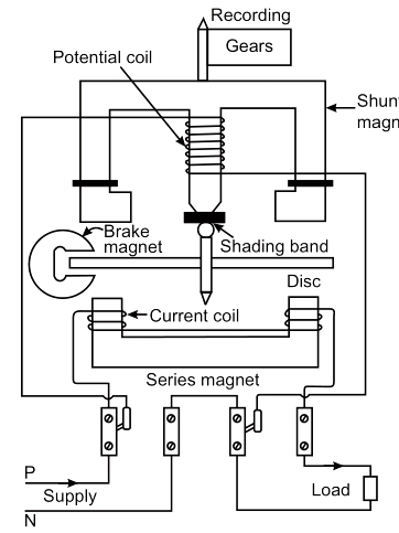
The driving system of the induction type single-phase energy meter consists of two electromagnets:
Series Magnet
Shunt Magnet
Series magnet in induction type Energy Meter consists of a number of U-shaped laminations of silicon steel staggered together to form a core.
A coil of thick wire having a few turns is wound on both the legs of a U-shaped magnet. This coil is connected in series with the load. Thus, it is excited by the circuit current or load current and is known as the current coil.
This magnet is placed below the aluminum disc and produces the magnetic field φse proportional to and in phase with line current.
Shunt magnet in induction type Energy Meter consists of a number of M-shaped laminations of silicon steel assembled together to form a core.
A coil of thin wire has a large number of turns in the wound on the central limb of the magnet.
This coil is connected across the load. Thus, it is excited by the current proportional to the supply voltage and is known as a potential or pressure coil.
4. Creep error may occur induction type energy meter due to
Incorrect position of brake magnet
Incorrect adjustment of the position of the shading band
Overvoltage across voltage coil
Increase in temperature
Answer.3. Overvoltage across voltage coil
Explanation:
Creeping in the induction type energy meter is the phenomenon in which the aluminum disc rotates continuously when only the voltage is supplied to the pressure coil and no current flows through the current coil.
The creeping increases the speed of the disc even under the light load condition which increases the meter reading.
Vibration, stray magnetic field, and the extra voltage across the potential coil are also responsible for the creeping.
The creeping error occurs because of excessive friction. The main driving torque is absent at no load. Hence the disc rotates because of the additional torque provided by the compensating vane.
5. Series electromagnet in induction type energy meter consists of _______
L shaped laminations
T shaped laminations
U shaped laminations
Y shaped laminations
Answer.3. U shaped laminations
Explanation:
Series magnet in induction type Energy Meter consists of a number of U-shaped laminations of silicon steel staggered together to form a core.
A coil of thick wire having a few turns is wound on both the legs of a U-shaped magnet. This coil is connected in series with the load. Thus, it is excited by the circuit current or load current and is known as the current coil.
This magnet is placed below the aluminum disc and produces the magnetic field φse proportional to and in phase with line current.
6. Which energy meter system contains a rotating aluminum disc that is placed between the air gaps of series and shunt magnets and mounted on a shaft?
Magnetic Flux
Moving System
Registering System
Driving System
Answer.2. Moving System
Explanation:
Moving system of Induction Type Energy Meter:
It consists of a light aluminum disc mounted on a vertical spindle.
The aluminum disc is positioned in the air gap between the series and the shunt magnet.
The spindle is supported by a cup-shaped jeweled bearing at the bottom end and has a spring journal bearing at the top end. Since there is no control spring, the disc makes continuous rotation under the action of deflecting torque.
7. Shunt magnet in induction type energy meter consists of _______
N shaped laminations
E shaped laminations
S-shaped laminations
M shaped laminations
Answer.4. M shaped laminations
Explanation:
Shunt magnet in induction type Energy meter consists of a number of M-shaped laminations of silicon steel assembled together to form a core.
A coil of thin wire has a large number of turns in the wound on the central limb of the magnet.
This coil is connected across the load. Thus, it is excited by the current proportional to the supply voltage and is known as a potential or pressure coil.
8. If an energy meter makes 5 revolutions in 100 seconds when a load of 225 W is connected, the meter constant is
800 rev/kWh
222 rev/kWh
147 rev/kWh
13 rev/kWh
Answer.1. 800 rev/kWh
Explanation:
Meter constant (K) = No. of revolution by meter / Energy consumed (E)
E (in kWh) = voltage x current x cos ϕ × time x 10-3 = Load × time x 10-3
Where, cos ϕ = power factor
Calculation:
Load power = 225 W, time = 100 sec, Number of revolutions = 5
Energy supplied in 100 seconds
= (225 × 100 × 10−3)/3600 = 6.25 × 10⁻³ kWh
Number of revolutions in 100 seconds = 5
Meter constant = number of revolutions / kWh
Meter constant = 5/6.25 × 10−3 = 800 rev/kWh
9. The shunt magnet in the single-phase Induction type energy meter is wound with
Large turns of wire
Small turns of wire
Medium turns of wire
No turns or wires
Answer.1. Large turns of wire
Explanation:
Shunt magnet in induction type energy meter consists of a number of M-shaped laminations of silicon steel assembled together to form a core.
A coil of thin wire has a large number of turns in the wound on the central limb of the magnet.
This coil is connected across the load. Thus, it is excited by the current proportional to the supply voltage and is known as a potential or pressure coil.
This magnet is placed above the aluminum disc.
10. The kWh meter can be classified as a / an instrument:
Indicating
Deflecting
Digital
Integrating
Answer.4. Integrating
Explanation:
Integrating Instruments: These instruments record the consumption of the total quantity of electricity, energy etc. during a particular period of time. These instruments give reading for a specific period of time but no indication of reading for a particular instant of time.
Example: Ampere-hour meter, Energy (kWh) meter, kilovolt ampere-hour meter.