1. In vector impedance meter, the coverage of instrument can be obtained with
V-I characteristics of the test system
Power-frequency plot
Sweep frequency plots of impedance and phase angle versus frequency
Voltage-angle plot
Answer.3. Sweep frequency plots of impedance and phase angle versus frequency
Explanation:
The Vector Impedance Meter is employed for measuring both the amplitude and phase angle of impedance (Z).
Impedance can be obtained in polar form
Its coverage can be obtained with a sweep frequency plot of impedance and phase angle versus frequency.
2. For measurement of which of the following is a Low Power Factor (LPF) wattmeter NOT suitable?
Measurement of power in inductive loads
Open circuit test on single-phase transformer
Measurement of power in resistive loads
Load test on induction motor
Answer.3. Measurement of power in resistive loads
Explanation:
The low power factor meter measures the low value of the power factor accurately known as the Low Power Factor Wattmeter (LPFW). The low power factor meter is used for measuring the power of the highly inductive circuit.
The ordinary Wattmeter used for measuring the low power factor gives an inaccurate result. This happens because of two reasons.
In a low power factor meter, the magnitude of deflecting torque on the moving coil is small even after the full excitation of the pressure and current coil.
The error occurs in the reading because of the pressure coil inductance.
It is not suitable for the measurement of power in resistive loads.
3. IEC 61000-4-15 defines the methodology and specification of instrumentation for
Measuring flicker
THD
Power frequency variation
All of the above
Answer.1. Measuring flicker
Explanation:
IEC 61000-4-15 gives a functional and design specification for flicker measuring apparatus intended to indicate the correct flicker perception level for all practical voltage fluctuation waveforms. Information is presented to enable such an instrument to be constructed.
A method is given for the evaluation of flicker severity on the basis of the output of flicker meters complying with this standard.
The flicker meter specifications in this part of IEC 61000 relate only to measurements of 120 V and 230 V, 50 Hz and 60 Hz inputs.
4. Which of the following is an advantage of electrodynamic type power factor meters?
Working forces are small as compared to moving iron-type instruments.
The scale is not extended over 360°.
They have high torque to weight ratio.
Calibration of electrodynamometer-type instruments is highly affected by changing the supply voltage frequency
Answer.3. They have high torque to weight ratio.
Explanation:
Advantages of Electrodynamic Type Power Factor Meters
Air cored coils are used, they are generally free from hysteresis and eddy current errors when used on AC circuits.
These instruments can be used for both DC. and AC measurements.
They have high torque to weight ratio.
It has precision grade accuracy when used as a wattmeter.
Less power consumption.
Disadvantages of Electrodynamic Type Power Factor Meters
Working forces are small as compared to moving iron-type instruments.
The scale is not extended over 360o.
The calibration of electrodynamometer-type instruments is highly affected by changing the supply voltage frequency.
They are quite costly as compared to other instruments.
5. In a digital frequency meter, the Schmitt trigger is used for
Converting sinusoidal waveforms into rectangle pulses
Scaling of sinusoidal waveforms
Providing timebase
Triggering a start pulse
Answer.1. Converting sinusoidal waveforms into rectangle pulses
Explanation:
A digital frequency meter is a general-purpose instrument that displays the frequency of a periodic electrical signal to an accuracy of three decimal places.
Working principle:
The unknown frequency signal is fed to the Schmitt trigger. This signal may be amplified before being applied to the Schmitt trigger.
In a Schmitt trigger, the sinusoidal signal is converted into a square wave with very fast rise and fall times, then differentiated and clipped.
As a result, the output from a Schmitt trigger is a train of pulses, one pulse, for each cycle of the signal.
The output pulses from the Schmitt trigger are fed to a start/stop gate when this gate opens (start), the input pulses pass through this gate and are fed to an electronic counter which starts registering the input pulses.
6. In which type of frequency meter, the frequency is found when the torque’ in the moving coil becomes zero?
Vibrating reed type
Permanent Magnet Moving Coil type
Moving iron type
Electrical resonance type
Answer.4. Electrical resonance type
Explanation:
The electrical resonance type frequency meter is an indicating type instrument.
Its action depends upon the electrical resonance.
It mainly consists of a fixed coil and a moving coil. There is a laminated iron core of varying cross-sections.
This varying laminated core holds the fixed coil at its one end. Then we connect this fixed coil across the supply mains.
In the Electrical resonance type frequency meter, the frequency is found when the torque in the moving coil becomes zero.
Torque Equation:
Let us consider I1 as the supply current of the fixed coil and I2 as the induced current of the moving coil.
We have the phase angle between the supply current I1 (current in the fixed coil) and the emf induced in the moving coil is 90°.
Again there is a phase difference between the induced emf and the induced current I2 (current in the moving coil).
Let us consider the angle of this phase difference is α.
So, the actual phase difference between I1 and I2 will be (90° – α).
Therefore, we can write the expression of the torque (T) as,
T = I1I2 cos (90° – α)
From the above expression of the torque, we can see that the torque will be zero when α is zero.
That means there must not be any phase difference between the induced current and the induced emf in the moving coil.
7. Working principle of Weston type frequency meter is based on which of the following principles?
Deflection
Speed
Light
Reflection
Answer.1. Deflection
Explanation:
The Weston frequency meter is a moving iron instrument used for measuring the unknown frequency of a signal.
A Weston type frequency meter is based on the principle of deflection.
It consists of 2 coils, which are resistive coil and an inductive coil.
The current in the coil changes, whenever the signal frequency deviates from the standard frequency.
The deflection of the pointer will move towards a higher magnetic field.
8. An LPF wattmeter of power factor 0.2 is having three voltage settings 300 V, 150 V, 75 V and two current settings 5 A and 10 A. The full-scale reading of the wattmeter is 150 W. If the wattmeter is used with 150 V voltage setting and 10 A current setting, the multiplying factor of the wattmeter is
4
2
6
8
Answer.2. 2
Explanation:
Multiplying factor is given by
MF = VICosφ/Full scale Power
Voltage = 150 V
Current = 10 A
PF = 0.2
Full scale power = 150 W
MF = (150 × 10 × 0.2)/150
MF = 2
9. While using a frequency counter for measuring frequency, two modes of measurement are possible. I) Period mode ii) Frequency mode. There is a ‘cross-over frequency’ below which the period mode is preferred. Assuming the crystal oscillator frequency to be 4 MHz the cross-over frequency is given by
8 MHz
2 MHz
2 kHz
1 kHz
Answer.3. 2 kHz
Explanation:
Let
fx = unknown frequency
fc = crystal frequency
fo = crossover frequency
Then, If fx < fo periodic mode
And fx > fo frequency mode
Now crossover frequency fo = √fc
fo = √4 × 106 = 2 × 10³
fo = 2 kHz
10. Which of the following bridges is used to measure power factor?
Wien’s bridge
Maxwell bridge
Schering bridge
Kelvin bridge
Answer.3. Schering bridge
Explanation:
Schering bridge is used to measure the relative permittivity, dielectric loss, and power factor of a capacitor.
Advantages of Schering Bridge
Balance equations are free from frequency.
The arrangement of the bridge is less costly compared to the other bridges.
11. Which of the following bridges is used to measure power factor?
Wien’s bridge
Maxwell bridge
Schering bridge
Kelvin bridge
Answer.1. Wien’s bridge
Explanation:
The Wien’s bridge is used in AC circuits for determining the value of unknown frequency. The bridge measures the frequencies from 100Hz to 100kHz.
The accuracy of the bridges lies between 0.1 to 0.5 percent. The bridge is used for various other applications like capacitance measurement, the harmonic distortion analyzer, and an HF frequency oscillator.
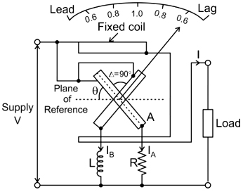
12. Power factor meters have
Only current coil
Only voltage coil
Both current and voltage coil
Only inductive voltage coil
Answer.3. Both current and voltage coil
Explanation:
The power factor meter measures the power factor of a transmission system.
The power factor meter determines the types of load used on the line, and it also calculates the losses that occur on it.
The meter has one fixed coil which acts as a current coil. This coil is split into two parts and carries the current under test.
The meter has two identical pressure coils A and B. Both the coils are pivoted on the spindle.
The pressure coil A has no inductive resistance connected in series with the circuit, and the coil B has a highly inductive coil connected in series with the circuit.
The current in coil A is in phase with the circuit while the current in coil B lag by the voltage nearly equal to 90°.
The meter has two deflecting torque one acting on coil A, and the other is on coil B. The windings are so arranged that they are opposite in directions. The pointer is in equilibrium when the torques are equal.
13. A pointer is connected to the spindle of a dynamometer-type phase angle meter. The two light coils of the phase angle meter mounted on the spindle
Carry equal amount of currents in phase with each other and develop torques opposing each other
Carry unequal amount of currents in phase with each other and develop torques opposing each other
Carry equal amount of currents at quadrature to each other and develop torques opposing each other
Carry the load current and develop the magnetic field required for the meter
Answer.1.
Explanation:
Electrodynamic Power Factor Meter is also known as the Dynamometer phase angle meter and Dynamometer power factor meter.
It measures the power factor or cosine of the phase angle between voltage and current.
There are 2 stationary coils (SC) also called current coils that are connected in series to the load.
The current coil produces a magnetic field proportional to the current.
There are 2 moving coils (MC) also called voltage or pressure coils, that are connected parallel to the load.
One moving coil is connected with a high resistor while another with a high inductor. These 2 coils make separation of 90° electrical.
The coils are arranged in such a way that 2 equal and opposite torques are produced and the pointer shows the desired result.
Therefore, there is no requirement for a controlling system.
14. A 3-phase moving coil type power factor meter has three fixed and symmetrically spaced current coils, inside of which are three other similarly placed moving potential coils. While in operation, the rotating magnetic field is produced in the
Current coils but not in the potential coils
Potential coils but not in the current coils
Both potential coil and the current coils
Neither the potential coils nor the current coils
Answer.3. Both potential coil and the current coils
Explanation:
Three-phase power factor is an electric instrument, used to measure the power factor.
Three current coils produce alternating flux and it acts on the pointer to deflect.
The angular deflection of the pointer gives the phase angle ϕ.
The rotating field of the coils of the 3-phase turns the moving pointer continuously in the direction of rotating flux.
The moving pointer is a potential coil. The flux produced by the current coil is linked with both the current and potential coil.
Moving potential coil is made up of high resistive material to reduce the effect of eddy current.
15. The Power factor of a sawmill is about
0.5
0.8
0.1
0.9
Answer.1. 0.5
Explanation:
The Power factor of saw mill is in the range of 0.45-0.60.