1. Induction-type wattmeter instruments are used for _______
AC Measurement
DC Measurement
AC and DC Measurement
None of the above
Answer.1. AC Measurement
Explanation:
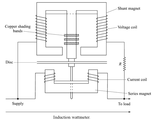
The induction type wattmeter can be used to measure AC power only. The working of induction type wattmeter is based on the principle of electromagnetic induction. The induction wattmeter consists of two laminated electromagnets viz. Shunt Magnet and Series Magnet.
2. The two laminated iron-core electromagnets are _____
Shunt Magnets
Series Magnets
Shunt and Series Magnets
Bar Magnets
Answer.3. Shunt and Series Magnets
Explanation:
The induction type wattmeter can be used to measure AC power only. The working of induction type wattmeter is based on the principle of electromagnetic induction. The induction wattmeter consists of two laminated electromagnets viz. Shunt Magnet and Series Magnet.
The shunt magnet is excited by the current, proportional to the voltage across the load. flowing through the pressure coil and the series magnet is excited by the load current or a definite fraction of it flowing through the current coil.
3. The disc of the Induction type wattmeter is made up of _____
Copper
Aluminum
Either copper and Aluminium
Steel
Answer.3. Either copper and Aluminium
Explanation:
A thin disc made of copper or aluminum pivoted at the center is placed between the shunt and series magnets so that it cuts the flux from both of the magnets. The deflecting torque is produced by the interaction of eddy currents induced in the discs and the flux inducing it.
In order to cause the resultant flux in the shunt magnet to lag in phase by exactly 90° behind the applied voltage. one or more copper rings, known as copper-shading bands are provided on one limb of the shunt magnet.
4. The deflecting torque in shunt and series magnets is produced due to _____
Hysteresis Current
Eddy Current
Electromagnetic Current
Both Eddy and Hysteresis current
Answer.2. Eddy Current
Explanation:
A thin disc made of copper or aluminum pivoted at the center is placed between the shunt and series magnets so that it cuts the flux from both of the magnets. The deflecting torque is produced by the interaction of eddy currents induced in the discs and the flux inducing it.
In order to cause the resultant flux in the shunt magnet to lag in phase by exactly 90° behind the applied voltage. one or more copper rings, known as copper-shading bands are provided on one limb of the shunt magnet.
5. The series magnet in induction type wattmeter is excited by the _______
Supply Current
Load Current
Load Voltage
Supply Voltage
Answer.2. Load Current
Explanation:
Series magnet in induction type wattmeter consists of a number of U-shaped laminations of silicon steel staggered together to form a core.
A coil of thick wire having a few turns is wound on both the legs of a U-shaped magnet. This coil is connected in series with the load. Thus, it is excited by the circuit current or load current and is known as the current coil.
This magnet is placed below the aluminum disc and produces the magnetic field φse proportional to and in phase with line current.
6. The shunt magnet in induction type wattmeter is excited by the _______
Supply Current
Load Current
Load Voltage
Current proportional to supply voltage
Answer.4. Current proportional to supply voltage
Explanation:
Shunt magnet in induction type wattmeter consists of a number of M-shaped laminations of silicon steel assembled together to form a core.
A coil of thin wire has a large number of turns in the wound on the central limb of the magnet.
This coil is connected across the load. Thus, it is excited by the current proportional to the supply voltage and is known as a potential or pressure coil.
This magnet is placed above the aluminum disc.
7. The series magnets in the Induction type wattmeter are wound with
Thick wire having Few turn
Thin wire having few turn
Thick wire having large turn
Thin wire having large turns
Answer.1. Thick wire having Few turn
Explanation:
Series magnet in induction type wattmeter consists of a number of U-shaped laminations of silicon steel staggered together to form a core.
A coil of thick wire having a few turns is wound on both the legs of a U-shaped magnet. This coil is connected in series with the load. Thus, it is excited by the circuit current or load current and is known as the current coil.
This magnet is placed below the aluminum disc and produces the magnetic field φse proportional to and in phase with line current.
8. The shunt magnet in the Induction type wattmeter is wound with
Thick wire having Few turn
Thin wire having few turn
Thick wire having large turn
Thin wire having large turns
Answer.4. Thin wire having large turns
Explanation:
Shunt magnet in induction type wattmeter consists of a number of M-shaped laminations of silicon steel assembled together to form a core.
A coil of thin wire has a large number of turns in the wound on the central limb of the magnet.
This coil is connected across the load. Thus, it is excited by the current proportional to the supply voltage and is known as a potential or pressure coil.
This magnet is placed above the aluminum disc.
9. In an induction type wattmeter the current in the pressure coil must _____ the supply voltage by ______.
Lead, 90°
Lag, 45°
Lag, 90°
Lead, 30°
Answer.3. Lag, 90°
Explanation:
In order to obtain deflecting torque in an induction type wattmeter, the current in the pressure coil must lag behind the supply voltage by 90°.
For this, a copper shading band (short-circuiting copper ring) is provided on the central limb of the shunt magnet. The phase difference of 90° is obtained by adjusting the position of this shading band.
The shading band acts as short-circuited transformer secondary.
Since its resistance is negligibly small as compared to its inductance, and therefore, current circulating in the shading band lags behind the supply voltage nearly by 90°.
10. The type of damping used in induction type energy meter is
Fluid friction damping
Air friction Damping
Electromagnetic Damping
Eddy current Damping
Answer.4. Eddy current Damping
Explanation:
The eddy current damping is used in the induction-type energy meter.
A permanent magnet positioned near the edge of the aluminum disc is used to provide necessary damping.
When aluminum disc moves in the field of the permanent magnet, flux is cut and eddy currents are induced in the disc.
The direction of induced currents is such that it opposes the rotation (Lenz’s Law), and thus, damping torque is produced.
Since the induced currents are proportional to the speed of the disc (N), the damping torque is proportional to the disc speed.
11. The shading band in induction type wattmeter is used to obtain _____
Deflecting Torque
Phase Difference
Phase Difference and Deflecting Torque
Extra Power
Answer.3. Phase Difference and Deflecting Torque
Explanation:
In order to obtain deflecting torque in an induction type wattmeter, the current in the pressure coil must lag behind the supply voltage by 90°.
For this, a copper shading band (short-circuiting copper ring) is provided on the central limb of the shunt magnet. The phase difference of 90° is obtained by adjusting the position of this shading band.
The shading band acts as short-circuited transformer secondary.
Since its resistance is negligibly small as compared to its inductance, and therefore, current circulating in the shading band lags behind the supply voltage nearly by 90°.
12. The current transformer is used in conjunction with an induction type wattmeter for the current level above _____
50 A
100 A
10 A
30 A
Answer.2. 100 A
Explanation:
In an induction type wattmeter, the currents upto about 100 A can be dealt with directly in such instruments. For currents above this, current transformers are used in conjunction with the wattmeter.
13. What are the advantages of the Induction type wattmeter?
Good damping
Uniform scale
Both 1 and 2
Low power consumption
Answer.3. Both 1 and 2
Explanation:
Advantages of Induction Type Wattmeter :
When compared with dynamometer wattmeters. these instruments have the advantages of greater working torque and length of the scale.
The scale is uniform.
They provide good damping.
There is no effect of stray fields.
14. The voltage transformer is used in conjunction with an induction type wattmeter for the voltage level above _____
750 V
200 V
1000 V
500 V
Answer.1. 750 V
Explanation:
In an induction type wattmeter the voltage level upto about 750 V can be dealt with directly in such instruments. For voltage above this, potential transformers are used in conjunction with the wattmeter.
15. What are the main disadvantages of the Induction type wattmeter?
High power consumption
Low accuracy
Temperature effect
All of the above
Answer.4. All of the above
Explanation:
When compared with dynamometer wattmeters. these instruments have certain inherent disadvantages. For example. they have less accuracy, the greater weight of the moving system. and greater power consumption, and they can be used only for the measurement of power on a.c. circuits. Since induction instruments are highly susceptible to variation in temperature and frequency. therefore induction wattmeters have industrial accuracy only at a stated frequency and temperature.
Disadvantages of Induction Type Wattmeter
Can be used only for ac power measurements.
Low accuracy due to heavy moving system.
Temperature changes can affect the readings by introducing errors.
Power consumption is more.
16. Induction-type wattmeters can be used only with circuits having
Steady Frequency
Steady Voltage
Both Steady Frequency and Voltage
Fluctuating Frequency and Voltage
Answer.3. Both Steady Frequency and Voltage
Explanation:
Induction-type wattmeters, in contradiction to electrodynamometer-type wattmeters, can be used only with circuits having relatively steady values of frequency and voltage.