
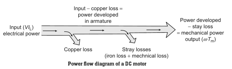
Losses in DC machine
A DC machine is an electromechanical energy conversion device. It can convert mechanical power into DC electrical power and is known as a DC generator. On the other hand, when it converts DC electrical power into mechanical power, it is known as a DC motor.
According to the law of conservation of energy “Energy can neither be created not be destroyed”. It is an ideal case where all the input power is converted into output power. Unfortunately, not all electrical power is converted to mechanical power by a D.C motor and not all mechanical power is converted to electrical power by a D.C generator.
The whole of the input power cannot be converted into the output power in a practical machine due to various losses that take place within the machine. Efficiency η being the ratio of output power to input power is always less than 1 (or 100%). A motor manufacturer will try to make η as large as possible.
The order of efficiency of a rotating dc machine is about 80% to 85%. It is therefore important to identify the losses which make efficiency poor. The losses will determine the heating of the machine and hence the rating or power output that can be obtained without insulation failure.
Various types of losses occur in different parts of DC machines. Though different losses are produced in different ways, all of them cause heating. The heat generated by these losses has two major serious effects. Losses in DC machine cause 2 main effect:-
- It increases the temperature inside the machine which affects the performance and life of the material of the machine, particularly insulation. Hence, the machine rating is directly affected by the losses.
- Ultimately, losses are a waste of energy. In other words, it is a waste of money because these losses increase the operating cost of the machine.
Types of Losses in DC machine
There are five categories of losses occurring in a dc motor similar to a dc generator.
- Electrical or Copper losses (I2R Losses)
- Core Losses or Iron Looses
- Mechanical losses
- Brush Losses
- Stray Load Losses
Electrical or Copper losses (I2R Losses)
- Resistive losses in the armature and field windings of the machine are called electrical or copper losses or Ohmic losses.
- This loss varies with the variation of load on the machine and is called variable loss. When a motor is loaded, its armature current increases. This increases the losses due to the armature resistance, so the copper losses in a motor increase with load. It varies as the square of the load current. If the load current is halved, the I2aRa loss will be one-fourth and so on.
- For a shunt machine, the field copper loss will be constant if field resistance is not varied.
- The power lost across the contact potential at the brushes of the machine (brush losses) is also included in these losses.
- The resistance of the armature winding can be measured by the ammeter-voltmeter method. By knowing the value of R. at room temperature, its value at operating temperature can be calculated.
- This loss is about 20% to 30% of full-load losses.
- In general, the various cooper losses in the DC machine are as follows.
- Armature copper loss = I2aRa
- Shunt field copper loss = I2shRsh
- Series field copper loss = I2seRse
- Interpole winding copper loss = I2iRi
- Brush contact loss = I2aRb = 2IaVb
- Compensating winding copper loss =I2aRc
Core Losses or Iron Looses
Core losses are also known as iron losses or Magnetic losses. Core losses can be classified into two types:-
- Hysteresis Losses
- Eddy current Losses
Hysteresis Losses:-
- The armature core is made up of magnetic material and is subjected to variations in magnetic flux. When the armature rotates it comes under North and South poles alternately.
- Hysteresis loss occurs due to the alternate magnetization of the atoms, forming domains in the magnetic material of the core. Each domain behaves like a tiny magnet that aligns itself with the magnetic flux in which it is placed.
- As the flux changes its direction (due to the changing of position of the rotor when the rotor rotates), these tiny magnets rotate to and fro.
- Power is wasted due to this movement and this process develops heat in the armature core. Hysteresis loss depends upon flux density and frequency of variation of flux.
- When the armature core passes under one pair of poles, the core is said to complete one cycle of frequency reversal. The frequency of magnetic reversal f = PN/120 Hz, where P is the number of poles. N is the speed of the armature in RPM.
The Hysteresis Losses can be obtained as
Hysteresis Loss = Kh.V.f.Bm1.6
Where
Kh = hysteresis constant given in J/m2. Its value depends on the nature of the material.
Ke = constant called co-efficient of eddy current. Its value depends on the nature of the material.
V = volume of the magnetic material in m3.
t = thickness of the lamination in m.. f = frequency of the magnetic reversal in cycles/second.
Bm = max. flux density in the magnetic material in Wb/m2.
- These losses vary as the square of the flux density (B2), volume of the core material and, for the rotor, as the 1.5th power of the speed of rotation (n1.5).
- To reduce hysteresis losses, high-grade steel with higher silicon content is used to reduce the friction of the magnetic materials and therefore reduce the heat produced in changing the magnetic fields of the motor iron.
To reduce the eddy currents, the laminations are sliced thinner and electrically insulated from one another. In addition, by lengthening the core, there is less flux density in the core material and reduced losses due to magnetic effects.
Eddy current loss:
Eddy current loss is due to the presence of circulating current in the core material. The armature core cuts the magnetic flux during its rotation and EMF is induced in the body of the core according to the laws of electromagnetic induction. This emf is very small but it sets up a large current in the body of the core. This EMF causes a circulating current ic in the core which is wasted as ic2.rc and produces heat.
Eddy current losses can be obtained as
Eddy current losses = Ke × Bm2 × f2 × t2
Where
Ke = Eddy current constant
t = thickness of the core
Bm = max. flux density in the magnetic material in Wb/m2.
- Eddy current loss depends upon flux density, frequency of alternation flux, the thickness of laminations used, and the volume of the core material.
- Iron losses are constant for shunt and compound generators, as their field currents are approximately constant. This loss is about 20% to 30% of the full-load loss.
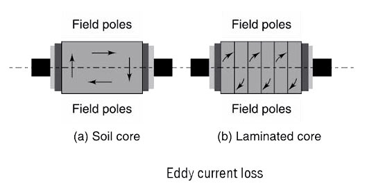
- To reduce eddy current loss in the core, the core is made up of varnished, laminated steel sheets instead of a solid core. This causes an increase of resistance, r, through which the eddy current flows.
- We know that the resistance of any material inversely proportional to its cross-sectional area. Figure (a) shows how eddy current induced in an armature core when the core is made of a solid piece of soft iron.
- Figure(b) shows a soft iron core of the same size as in the previous case but made up of a number of small pieces insulated from each other. This process is known as lamination.
- The current in each lamination is considerably lesser than that in the solid core because the resistance of the lamination is much higher due to the reason stated above, i.e., resistance is inversely proportional to the cross-sectional area. The sum of the individual currents in all the laminations is also much lesser than that produced in the solid iron core.
Mechanical Losses:
The mechanical losses in a dc machine are the losses associated with mechanical effects. Mechanical losses occur at the bearing and shaft and air friction (windage loss) due to rotation of the armature.
There are two basic types of mechanical losses:
- Friction
- Windage.
Frictional losses take place due to the rotation of the armature. These losses are a bearing-friction loss, brush-friction loss, and windage-friction loss. Windage-friction loss takes place due to the rotation of the armature in air. Windage-friction loss is proportional to the cube of the speed. Brush-friction loss and bearing-friction loss are proportional to the speed. This loss is about 20% to 30% of full-load losses. For practically constant speed operation, this loss too may be assumed to be constant.
Bearing friction loss generally depends on the type of bearing used and on the viscosity of the lubricant.
Brush friction loss is proportional to the contact area and the brush pressure. It also depends on the other factors like material of the brush and commutator, their polish condition, and the temperature at the contact surface.
Stray Load Looses
- The magnetic and mechanical losses are known as stray losses. Stray losses are also known as rotational losses.
- Stray losses make up the remaining motor losses. Stray losses occur because the magnetic flux created in the stator is lost and never reacts with the rotor conductors to produce torque.
- By lengthening the core, stray losses are reduced. To accomplish all these reductions in losses, redesigns were needed.
- Stray load losses are losses that are produced in the machine when they are loaded. They cannot be considered with the main losses listed above. These losses include:(a) Additional core loss resulting from armature reaction distortion. (b) Copper loss due to short circuit produced in coils, segments, and brushes during commutation.(c) Copper loss due to non-uniform distribution of current in large-sized armature conductors.
Stray load losses are very small in value and therefore, they are very difficult to calculate. In small machines, they can be neglected but for large machines, they are generally considered to be 1% of the output power in total.
Constant and Variable Losses
For a DC Machine,
Total Losses = Constant losses + Variable losses
Constant losses are those losses that always occur irrespective of the load conditions and whose value remains constant for a given machine. Mechanical losses, core losses, and shunt field copper losses are included in constant losses.
Variable losses are those losses which increase as the load on the machine is increased. They are electrical losses including armature copper losses, the field winding copper losses, interpole winding copper losses, compensating winding copper losses, and brush contact losses.
Copper losses increase proportionally to the square of the armature current while brush contact losses increase proportionally to armature current. At full load, constant losses are 4% to 20% and variable losses are 3% to 6%.
Stray load losses do not have a fixed value. They are somehow related to armature current and speed. Since they are complicated to compute and are very small in value, they are mostly ignored.
BRUSH LOSSES.
The brush drop loss is the power loss across the contact potential at the brushes of the machine. It is given by the equation
PBD = VBD.IA
Where
PBD = Brush drop loss
VBD = Brush Voltage drop
IA = Armature current
Point to Remember
- Armature copper loss about 30 to 35% of full-load losses.
- Field copper loss about 20 to 30%t of full-load losses.
- Iron losses, about 20 to 30% of full-load losses.
- Mechanical losses, about 10 to 15% of full-load losses.