
Ques.91. Synchro is a transducer
- Variable reluctance
- Parabolic
- Angular position
- Synchronizing
Answer.3. Angular position Explanation: A synchros is an electromagnetic transducer commonly used to convert an angular position of the shaft into an electric signal. It is known as selsynorantosym, Telesyn. Basically, a synchros is a rotary device that operates on the same principle as the transformer and produces a correlation between angular position and a voltage or set of voltage. It is used to determine the magnitude and direction of angular displacement. Synchros are used widely in control systems as detectors and encoders because of their ruggedness in construction and high reliability. When the rotor positions of two synchros are in perfect alignment, the voltage generated across the terminal of output rotor winding is zero. Wher the rotor shafts are not aligned, the rotor voltage of control transformer is approximately a sine function of the difference between the two shaft angles.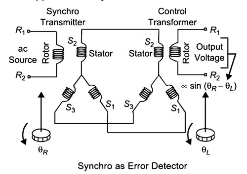
Ques.92. A cell in which a semiconductor having a negative illumination coefficient of resistance is used is known as
- Triode
- Photo-conductive cell
- Photo-voltaic cell
- Photometer
Answer.2. Photoconductive cell Explanation:- PHOTOCONDUCTIVE CELLS A photoconductor is a bulk semiconductor device, whose resistance varies inversely when the light is incident on its surface. All semiconductors can be considered as photoconductors. This is because any semiconductor will produce electron-hole pairs (EHP) when it is irradiated by electromagnetic radiation of the optical frequencies. These include frequencies in the infrared, visible and ultraviolet radiations. As we know that in semiconductors, energy gap exists between conduction electrons and valence electrons. Alden photons are absorbed in a photoconductive material, due to impartion of the photon energy, electrons are excited into the conduction band, reducing the resistance of the photoconductive material. The photoconductive cell is a two terminal semiconductor device whose resistance varies inversely with the intensity of light that falls upon its photosensitive material shows a typical photoconductive cell and the schematic symbol. These devices are also called photoresistive cells or photoresistors since the change in conductivity appears as a change in resistance. The photoconductive materials most frequently used include cadmium sulfide (CdS) and cadmium selenide (CdSc). The response time of CdS units is about 100 ms and of CdSe cells is 10 ms. 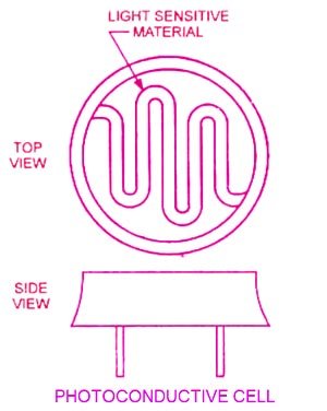
Ques.93. The sensitivity of a photo-electric cell is measured in terms of
- Current per unit of luminous flux
- Current per unit area of the surface
- Current per volt
- Luminosity per unit ampere
Answer.2. Current per unit area of the surface Explanation:- PHOTOELECTRIC DEVICE When light strikes certain light-sensitive materials, it may cause them to give off electrons, it may change their ability to conduct electricity, or it may cause them to develop an electrical potential, or voltage, across two surfaces. Devices that rely on these effects for their operation are called photoelectric devices. Photoelectric devices can be adapted to a variety of applications. As an optical switch that senses the interruption of a light beam, a photoelectric device can open doors automatically or activate a counter on an assembly line. Because the electric current put out by photoelectric devices varies with the intensity of the incoming light, the devices can be used as sensors to turn lights on at night and off during the day. Photoelectric devices can be made sensitive to certain wavelengths of incoming light and used in photographic light meters. They are also used in the reproduction of movie and soundtracks. Photoelectric units can also be made to operate in the infrared and ultraviolet regions of the electromagnetic spectrum (see radiation). The light beams in burglar alarms, for example, are usually outside the visible spectrum. The sensitivity of a photoelectric cell can be expressed in terms of luminous sensitivity (output current per incident visible light flux; μa/lumen) or in terms of radiant sensitivity (output current per incident radiation power, (μa/,μw).
Ques.94. Which cell has the highest sensitivity (current per unit of luminous flux)
- Vacuum photo-emissive cell
- Gas-filled photo-emissive cell
- Selenium photovoltaic cell
- Germanium junction photo-conductive cell.
Answer.4. Germanium junction photo-conductive cell.
Explanation:-
Photo-conductive cells, in which an incident photon removes an electron from the valence band into the conduction band. The value of the forbidden energy gap sets a long wave limit to the sensitivity of the photocell. A photoconductive cell appears as a linear resistance, which decreases with increased illumination.
Photo-conductive diodes operate with a reverse voltage of up to 100 V. The germanium junction photodiode has a maximum sensitivity of about 30mA/lumen at a light wavelength of 1.6 µ (or 16,000 A).
Ques.95. Which cell has the lowest sensitivity (current per unit of luminous flux)
- Vacuum photo-emissive cell
- Gas-filled photo-emissive cell
- Selenium photovoltaic cell
- Germanium junction photo-conductive cell.
Answer.1. Vacuum photo-emissive cell Explanation:- In photo emissive cells or phototubes, emission of electrons is caused by the energy of a light beam striking a metallic surface having a low work function. This sensitive surface is enclosed in a vacuum, a gas-filled envelope or quartz and the emitted electrons are captured by a positive anode. Photo~amissive cells are of two types. (i) Vacuum photo-emissive cell or phototube (ii) Gas-filled photoemissive cell or gas phototube. In the vacuum photo-tube, the cathodic surface is treated with a low work-function material and a small wire is used as an anode. The cathode is semicircular in appearance. The anode collects the electrons emitted when the light strikes the light-sensitive cathode. Anode voltages are large enough to achieve current saturation, i.e., all electrons emitted by voltages over about 40 volts reach the anode. The sensitivity of vacuum cells is low, being about 30 PA per lumen. The current output of a vacuum phototube is only a few micro-amperes, which is very small. To increase the current output and sensitivity for a given luminous flux, an inert gas, usually argon or neon, is introduced at low pressure to cause ionization. Ionization by the collision of electrons with gas molecules increases the current five to ten times. This effect is also Known as the thermionic effect.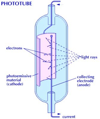
Ques.96. In an energy meter, the steady speed of disc can be achieved when
- Braking torque is zero
- Braking torque is more than operating the torque
- Operating torque is equal to or less than half the braking torque
- Operating torque is equal to the braking torque
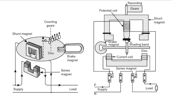
Answer.4. Operating torque is equal to the braking torque Explanation:- An induction-type instrument can be used as an ammeter, voltmeter, or wattmeter, the induction-type energy meters are more popular. Induction-type single-phase energy meter is used invariably to measure the energy consumed in an AC circuit in a prescribed period where supply voltage and frequency are constant. The energy meter is an integrating instrument that measures the total quantity of electrical energy supplied to the circuit in a given period. Principle The basic principle of induction-type energy meter is electromagnetic induction. When AC flows through two suitably located coils (current coil and potential coil), they produce the rotating magnetic field that is cut by the metallic disc suspended between the coils, and thus, an emf is induced in the disc that circulates eddy currents in it. By the interaction of rotating magnetic field and eddy currents, electromagnetic torque is developed that causes the disc to rotate. This is the same principle that is applied in single-phase induction motors. A single phase energy meter has four essential parts: Operating System The operating system consists of two electromagnets. The cores of these electromagnets are made of silicon steel laminations. The coils of one of these electromagnets (series magnet) are connected in series with the load and are called the current coil. The other electromagnet (shunt magnet) is wound with a coil that is connected across the supply, called the pressure coil. The pressure coil, thus, carries a current that is proportional to supply voltage. Shading bands made of copper are provided on the central limb of the shunt magnet. Shading bands, as will be described later, are used to bring the flux produced by a shunt magnet exactly in quadrature with the applied voltage. Moving System The moving system consists of a light aluminum disc mounted on a spindle. The disc is placed in the space between the series and shunt magnets. The disc is so positioned that it intersects the flux produced by both the magnets. The deflecting torque on the disc is produced by an interaction between these fluxes and the eddy current they induce in the disc. In energy meters, there is no control spring as such, so that there is the continuous rotation of the disc. Braking System The braking system consists of a braking device which is usually a permanent magnet positioned near the edge of the aluminum disc. The arrangement is shown in Figure. The emf induced in the aluminum disc due to relative motion between the rotating disc and the fixed permanent magnet (brake magnet) induces an eddy current in the disc. When disc rotates in the air gap, eddy currents are induced in the disc which opposes the cause producing them i.e. relative motion of disc with respect to the magnet. This eddy current, while interacting with the brake magnet flux, produces a retarding or braking torque. This braking torque is proportional to the speed of the rotating disc. When the braking torque becomes equal to the operating torque, the disc rotates at a steady speed. Driving torque Since the flux due to the pressure coil is proportional to its voltage V and the other flux acting on the disc is due to the current coil current, I, the driving torque, Td, on the disc is Td = VI cosφ where φ is the angle between V and I. Due to this driving torque Td, on the disc, it starts rotating. Braking torque The braking torque is proportional to the flux of the braking magnet and the eddy current induced in the moving system due to its rotation in the field of the braking magnet. TB ∝ φi where φ is the flux of the braking magnet and ‘i’ the induced current. Now i = e/R where e is the induced e.m.f. and R the resistance of the eddy current path. Also, e ∝ φn where n is the speed of the moving part of the instrument. ∴ TB ∝ φ × φn/R TB ∝ φ2n/R The braking torque Tb opposes the rotation of the disc. When the driving and braking torques are equal, the disc rotates at a steady speed and at the steady speed, the speed of the disc, The position of the permanent magnet with respect to the rotating disc is adjustable. Therefore, braking torque can be adjusted by shifting the permanent magnet to different radial positions with respect to the disc. By changing the distance between braking magnet and magnetic shunt, the braking torque can be adjusted. The braking torque increases when the distance between them is increased because of moving the magnetic shunt away from the magnet, it will bypass a less amount of flux and vice versa. Hence the Braking torque provided by a permanent magnet is proportional toInduction-type Single-phase Energy Meter
Ques.97. Which is the integrating instrument?
- Voltmeter
- Wattmeter
- Energy meter
- Power factor meter
Answer.3. Energy Meter Explanation:- Integrating instruments are those which measure the total amount of the electrical quantity (e.g. energy) supplied over a period of time. In such instruments, there are sets of dials or gears which register the total quantity of electricity or the total amount of electrical energy supplied to a circuit in a given period. Household energy meter is an integrating instrument. Ampere-hour meter another example of integrating instruments.
Ques.98. If the instrument has a wide range, the instrument should have___
- Square law scale
- Linear scale
- Exponential scale
- Logarithmic scale
Answer.4. Logarithmic scale
Explanation:-
Various Scales for measurement through an instrument are
1. Linear Scales:- A linear scale like a foot rule, is the simplest to read. Though termed as linear it may form a part of the arc, however, the graduations will be uniformly disturbed. The moving coil electrodynamic wattmeters generally have the linear scale. Moving iron instruments also have nearly linear scales.
2. Square low scale:- Some instruments like thermal instruments, electrodynamic voltmeters, and ammeters follow the square law scale.
3. Logarithmic scale:- The logarithm and its use is nothing more than a mathematical tool which simplifies dealing with very large and very small numbers. For example, the logarithm of the number 1,000,000 is six, and the logarithm of the number 0.000001 is -six (minus six). Obviously, as more zeros are added before or after the decimal point, convening these numbers to their logarithms greatly simplifies calculations which use these number.
If the current to be measured extends over a wide dynamic range, for example spanning several orders of magnitude, there is a risk that the signal conditioning circuit can saturate at its upper or lower limit and no measurement will be obtained. This problem can arise in the measurement of photocurrents in the atmosphere which span a large range of values during the daytime, and in atmospheric electricity measurements where currents generated in elevated points vary between HA in disturbed weather to pA in fair weather. An alternative approach for current measurement is therefore needed if, in preserving the capability to measure large currents, good resolution is still required at the low current end of the range.
A wide operating range can be achieved with a logarithmic current amplifier, which generates an output voltage proportional to the logarithm of the input current. This can be implemented with an opamp by using a device having an exponential voltage-current response in place of the feedback resistor of the trans-resistance configuration, such as a diode.
Similarly, we use logarithmic scales for things that come in an extremely wide variety of sizes. Earthquakes are just one example: a 9.0 earthquake releases a trillion times as much energy as a 1.0 earthquake.
If we used a linear scale, we would have to use giant numbers to describe earthquakes; for example, a 6.0 magnitude earthquake would be a 1,000,000,000 size earthquake, and a 9.0 magnitude earthquake would be described as a 1,000,000,000,000 size earthquake.
Ques.99. Holes are drilled on the opposite sides of the spindles of an energy meter to
- Avoid creep on load
- Balance the disc
- Dissipate heat generated due to eddy currents
- Increases the deflection torque
Answer.1. Avoid creep on load Explanation:- Error in single-phase Energy Meter (1) Phase Errors: Normally, the flux due to the shunt magnet does not lag behind the supply voltage by exactly 90° due to the fact that the coil has some resistance. Therefore, the torque is not zero at zero power factor. This is known as phase error and is compensated by means of an adjustable copper band placed over the central limb of the shunt magnet. Due to this reason, the shading ring is known as the power factor compensator. (2) Speed Error: The speed error of the meter, when tested on a non-inductive load, can be eliminated by correctly adjusting the position of the braking magnet. Movement of the poles of the braking magnet towards the center of the disc reduces the braking torque and vice-versa. (3) Friction Error: Frictional forces at the rotor bearings and in the register mechanism give rise to an unwanted braking torque on the disc rotor. This can be reduced by making the ratio of the shunt magnet flux and series magnet flux large with the help of two shading bands. Correct compensation is achieved when the rotor does not run on no-load with only supply voltage connected. (4) Creeping Error: The slow but continuous rotation of the disc when only the pressure coils are excited but no current is flowing in the circuit is called “creeping”. It may be caused by various factors like incorrect friction compensation, vibration, stray magnetic fields, or due to the voltage supply being in excess of the normal. To overcome this creeping effect on no-load, two holes are drilled in the disc on a diameter, i.e. on opposite sides of the spindle. This causes sufficient distortion of the field to prevent rotation when one of the holes comes under one of the poles of the shunt magnet. (5) Temperature Error: The error due to temperature variations of the instruments are usually small because the various effects produced tend to neutralize one another.
Ques.100. What is the percentage voltage error of a potential transformer with the system voltage of 11,000 V and having turns ratio of 100, if the measured secondary side voltage is 105 V?
- 2.75
- 3.55
- 4.76
- 9.09
Answer.3. 4.76 Explanation:- System voltage i.e Nominal voltage = 11000 V Voltage Transformation ratio of the potential transformer is V1/V2 = N1/N2 V1/105 = 100 Primary voltage = Turn ratio × Secondary voltage = 105 × 100 = 10500 V Percentage of error is the Potential error = (Nominal voltage − Primary voltage)/Primary voltage (11000 − 10500)/10500 = 4.76%
FOR TRANSMISSION AND DISTRIBUTION SYSTEM MCQ CLICK HERE
FOR DC MOTOR MCQ CLICK HERE
FOR 3-Φ INDUCTION MOTOR MCQ CLICK HERE
FOR SYNCHRONOUS GENERATOR OR ALTERNATOR MCQ CLICK HERE
FOR Electric Drive MCQ CLICK HERE