Ques.71. A meter has a constant of 600 revolutions per kWh. If the meter makes 10 revolutions in 20 seconds, what is the load in kW?
0.75 kW
1.5 kW
3 kW
6 kW
Answer.3.3kW
Explanation:-
Meter constant K = Number of revolution/Kwh (rev/kWh)
Number of revolution = 10
Energy consumed when the disc made 10 revolution
= 10 × 1/600 = 1/60 KWh
Now energy consumed is equal to load in kW multiplied by time in hours i.e.
Load × 20/3600 = 1/60
Load = 3600/120
Load = 3 kW
Ques.72. A 220 V single phase meter has a constant load current of 5.0 A passing through it for 2 hours, at unity power factor. If the meter disc makes 1056 revolution during this period. What is the meter constant in revolutions/kWh?
120
240
360
480
Answer.4.480
Explanation:-
Energy consumed in two hours = V.I.cosφ.t
Where
Voltage V = 220 V
Current I = 5 A
Power factor cosφ = 1
Time (t) = 2 hours
Number of revolution = 1056
Energy consumed = 220 × 5 × 1 × 2 = 2.2 kWh
Meter constant K = Number of revolution/Kwh (rev/kWh)
K = 1056/2.2 = 480 rev/kWh
Ques.73. A balanced three-phase star-connected load draws power from a 440 V supply. The two connected wattmeters, W1 and W2, indicate 5 kW and 1200 W. Calculate the total power.
5 kW
6,200 kW
62 kW
6,200 W
Answer.4.6200W
Explanation:-
The sum of two wattmeters gives the total power consumption in the three-phase load i.e
Total Power = P1 + P2
Reading of wattmeter 1
W1 = 5 kW = 5000 watts
Reading of wattmeter 2
W2 = 1200 watts
Total power = 5000 + 1200 = 6200 watts
Ques.74. The reading on the ammeters connected for the three ammeter method of power measurement is 2.0 A, 4 A and 6 A in the non-inductive resistor, the load and the main respectively. The terminal voltage is 300V. The non-inductive resistance of the load is
150 ohms
75 ohms
50 ohms
25 ohms
Answer.1.150Ω
Explanation:-
Given: I1 = 2.0 A; I2 =4 A; I3 = 6 A
V = 300 V
Non-inductive resistance, R = (V/I1) = 300/2 = 150Ω
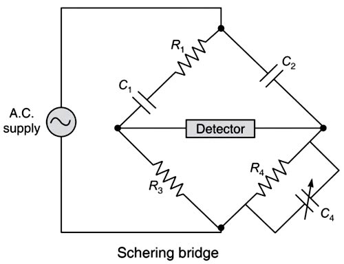
Ques.75. The bridge used to measure the dielectric loss of an insulator is
Anderson bridge
Wein’s bridge
Schering bridge
Any of the above
Answer.3.Schering bridge
Explanation:-
The Schering bridge is used for the measurement of the properties of insulators, capacitor bushings insulating oil, Dielectric losses, and other insulating material.
The loss factor is given as
R1 = R3C4/C2
Dissipation factor/Dielectric loss
C1 = C2R4/R3
It is suitable for small capacitances and usually supplied from high frequency or a high voltage source.
Note:-
The Anderson’s bridge gives the accurate measurement of self-inductance of the circuit.
Wien’s bridge is used for precision measurement of capacitance in terms of resistance and frequency. It is also used to measure audio frequencies.
Ques.76. Which of the following instrument can be used in ac bridges for less frequencies upto 200 Hz only?
Headphone
Tunable amplifier detector
Vibration galvanometer
All of the above
Answer.3.Vibration galvanometer
Explanation:-
A galvanometer is an instrument that is used to detect the presence and measure magnitudes of the small currents or voltages in the measuring circuits. Thus galvanometer term is generally used for any current or voltage indicating instrument which is not calibrated.
A.C Galvanometers: The A.C galvanometers are mainly used as a null detector in the bridge and potentiometer circuit. These are also used for measuring an effective or r.m.s. value of the small A.C current flowing in the circuit. The a.c. galvanometers are further classified as phase-sensitive galvanometers and frequency-sensitive galvanometers.
The phase-sensitive galvanometers are dynamometer-type galvanometers in which a moving system is suspended with a long suspension win a mirror attached to it. To make the instrument is highly sensitive, the moving system should be light. To protect the moving coil from the electrostatic field between fixed and moving coils it is necessary to screen the moving item properly. To increase the sensitivity of the instrument, a laminated iron core is used for the fixed coil to achieve a stronger magnetic field In this type of galvanometer, the magnetic field is setup by an a.c electromagnet.
The frequency selective galvanometer is called a tuned detector type galvanometer. It is tuned at an operating frequency and it is generally used at frequencies below 250 Hz as the galvanometer is found to be more sensitive than the telephone. The common frequency-selective galvanometer is the vibration galvanometer.
Vibration Galvanometers
Vibration galvanometers are the more sensitive bridge detectors and are constructed in the frequency range from 5 c/s to 1000 c/s but their principal application is below 200 cps where their sensitivity is greater than telephone receiver. At power frequency, their sensitivity closely matches with those of d.c. galvanometers. Thus the response of vibration galvanometer is limited to a very narrow range of frequency. When tuned to the fundamental frequency, it will have an extremely small response to harmonics. Vibration galvanometers are of two types:
(i) Moving-magnet-type vibration galvanometer
(ii) Moving-coil-type vibration galvanometer
Ques.77. Maxwell bridge is used to measure
Resistance
Inductance
Capacitance
Frequency
Answer.2.Inductance
Explanation:-
A Maxwell bridge is a modification to a Wheatstone bridge used to measure an unknown inductance (usually of low Q value) in terms of calibrated resistance and inductance or resistance and capacitance.
As in the balanced condition of the Wheatstone bridge product of opposite arms, resistance are equal i.e
R1R3 = R2R4
In Maxwell AC bridge in the two arms, there are two pure resistances so that for balance relations, the phase balance depends on the remaining two arms.
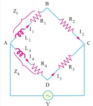
For the balanced condition of Maxwell AC bridge
Z1Z3 = Z2Z4
Where Z1 is the unknow Impedance
Z1 = R1 + JX1 = R1 + JωL1
Z4 is the know Impedance
Z4 = R4 + JX4 = R4 + JωL4
R2 and R3 = Known pure resistance
∴ (R1 + JωL1)R3 = (R4 + JωL4)R2
Equating Real and Imaginary part
R1R3 = R2R4
&
ωL1R3 = ωL4R2 L1R3 = L4R2
Hence, the unknown self-inductance can be measured in terms of the known inductance L4 and the two resistors. Resistive and reactive terms balance independently and the conditions are independent of frequency. This bridge is often used for measuring the iron losses of the transformers at audio frequency.
Ques.78. A bridge used for the measurement of capacitance is
Wheatstone bridge
Wein bridge
Maxwell bridge
Schering bridge
Answer.2.Wein bridge
Explanation:-
The Wien bridge is one of many common bridges. Wien’s bridge is used for the precision measurement of capacitance in terms of resistance and frequency. It is also used to measure audio frequencies. It is also used in distortion analyzers as the notch filter.
Ques.79.Determine the deflection sensitivity (in m/V) of a CRO, when the value of the deflection factor is 0.5 V/m.
1
2
3
4
Answer.2.2
Explanation:-
The deflection sensitivity of a magnetic deflection cathode ray tube is defined as the amount of spot deflection on the screen when the potential of 1 volt is applied to the deflection plate.
In most CROs, the deflection sensitivity is expressed as the ratio of input voltage to the length of the trace.
In the electrostatic deflection, the spot la deflected on the screen by applying voltages on the vertical or the horizontal deflecting plates. The dc or peak-to-peak ac voltage applied to the deflects ing plates to displace the spot by 1 mm on the screen is termed the deflection factor. The reciprocal of the deflection factor is called the deflection sensitivity. The deflection factor la usually expressed in V/mm and deflection sensitivity in mm/V.
Deflection sensitivity of the CRO is given as
Deflection sensitivity = 1/deflection factor
Deflection sensitivity = 1/0.5 = 2 m/V
Ques.80. A 100 V Voltmeter has an accuracy of 5% on the full scale. The percentage error while measuring 50 V will be
2.5%
5%
7.5%
10%
Answer.4.10%
Explanation:-
Limiting error at full scale is
δE = ± 5% of 100
δE = ±5mv
Thus when the reading is 50 V, the error will still be 5 V. Hence the % limiting error
= (5/50)x100 = 10%
Note that the percentage limiting error is twice the mentioned value at full-scale reading. The limiting error increases as the reading of the voltmeter decrease.