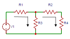
21. Consider the circuit shown below. The number mesh equations that can be formed are?
A. 1
B. 2
C. 3
D. 4
Answer: B
We know if there are n loops in the circuit, n mesh equations can be formed. So as there are 2 loops in the circuit. So 2 mesh equations can be formed.
22. In the figure shown below, the current through loop 1 be I1 and through loop 2 be I2, then the current flowing through the resistor R2 will be?
A. I1
B. I2
C. I1 − I2
D. I1 + I2
Answer: C
Through the resistor R2 both the currents, I1 and I2 are flowing. So the current through R2 will be I1 − I2.
23. If there are 5 branches and 4 nodes in the graph, then the number of mesh equations that can be formed is?
A. 2
B. 4
C. 6
D. 8
Answer: A
Number of mesh equations
= B − (N − 1).
Given a number of branches = 5 and number of nodes = 4.
So Number of mesh equations = 5 − (4 − 1) = 2.
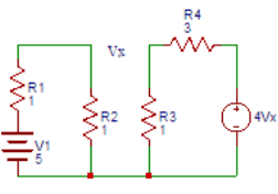
24. Consider the circuit shown in the figure. Find voltage Vx.
A. 1
B. 1.25
C. 1.5
D. 1.75
Answer: B
Consider current I1 (CW) in loop 1 and I2 (ACW) in loop 2.
So, the equations will be
Vx + I2 − I1 = 0.
I1 = 5/2 = 2.5A
I2 = 4Vx/4
= Vx. Vx + Vx − 2.5 = 0.
Vx = 1.25V.
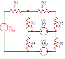
25. Consider the circuit shown below. Find the current I1.
A. 3.3
B. 4.3
C. 5.3
D. 6.3
Answer: B
According to mesh analysis,
(1 + 3 + 6)I1 – 3(I2) – 6(I3) = 10
− 3(I1) + (2 + 5 + 3)I2
= 4 − 6(I1) + 10(I3) = − 4 + 20
On solving the above equations, I1 = 4.3A.
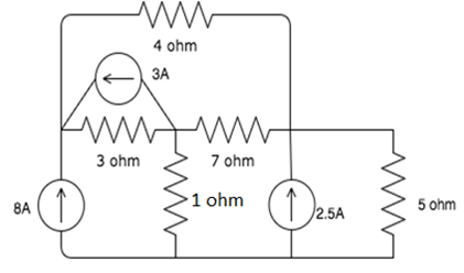
26. Consider the following figure. Find the current I2 (A)
A. 1.7
B. 2.6
C. 3.6
D. 4.6
Answer: A
According to mesh analysis
(1 + 3 + 6)I1 – 3(I2) – 6(I3) = 10.
− 3(I1) + (2 + 5 + 3)I2 = 4.
− 6(I11) + 10(I3) = − 4 + 20
On solving the above equations,
I2 = 1.7A.
27. Consider the following figure. Find the current I3 (A)
A. 4
B. 4.7
C. 5
D. 5.7
Answer: B
According to mesh analysis
(1 + 3 + 6)I1 – 3(I2) – 6(I3) = 10
− 3(I1) + (2 + 5 + 3)I2 = 4.
− 6(I1) + 10(I3) = − 4 + 20.
On solving the above equations, I3 = 4.7A.
28. Find the current through the R2 resistor.
A. 3
B. 3.25
C. 3.5
D. 3.75
Answer: D
Applying mesh analysis
5(I1) + 2(I1 − I2) = 10
10(I2) + 2(I2 − I1) + 40 = 0.
On solving
I1 = 0.5A, I2 = − 3.25A.
So current through R2 resistor is 0.5 − ( − 3.25) = 3.75 A
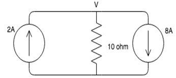
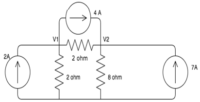
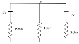
29. Find the value of the node voltage V of the given circuit.
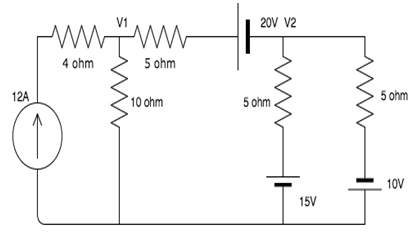
33. Find the voltage of V1 and V2 using Nodal Analysis.
A. 87.23V, 29.23V
B. 23.32V, 46.45V
C. 64.28V, 16.42V
D. 56.32V, 78, 87V
Answer: C
The nodal equations are:
0.3V1 − 0.2V2 = 16
− V1 + 3V2 = − 15
Solving these equations simultaneously, we get
V1 = 64.28V and V2 = 16.42V.
34. Nodal analysis is generally used to determine_______
A. Voltage
B. Current
C. Resistance
D. Power
Answer: A
The nodal analysis uses Kirchhoff’s Current Law to find all the node voltages. Hence it is a method used to determine the voltage.
35. If there are 10 nodes in a circuit, how many equations do we get?
A. 10
B. 9
C. 8
D. 7
Answer: B
One node is taken as a reference node so, the number of equations we get is always one less than the number of nodes in the circuit, hence for 10 nodes we get 9 equations.
36. Nodal analysis can be applied for ________
A. Planar networks
B. Non-planar networks
C. Both planar and non-planar networks
D. Neither planar nor non-planar networks
Answer: C
Nodal analysis can be applied for both planar and non-planar networks since each node, whether it is planar or non-planar, can be assigned a voltage.
37. How many nodes are taken as reference nodes in a nodal analysis?
A. 1
B. 2
C. 3
D. 4
Answer: A
In the nodal analysis, one node is treated as the reference node and the voltage at that point is taken as 0.
38. If there are 8 nodes in the network, we can get _________ number of equations in the nodal analysis.
A. 9
B. 8
C. 7
D. 6
Answer: C
Number of equations = N − 1 = 7.
So as there are 8 nodes in the network, we can get 7 number of equations in the nodal analysis.
39. Nodal analysis can be applied to non-planar networks also.
A. true
B. false
Answer: A
Nodal analysis is applicable for both planar and non-planar networks. Each node in a circuit can be assigned a number or a letter.
40. In nodal analysis how many nodes are taken as reference nodes?
A. 1
B. 2
C. 3
D. 4
Answer: A
In nodal analysis, only one node is taken as a reference node. And the node voltage is the voltage of a given node with respect to one particular node called the reference node.