
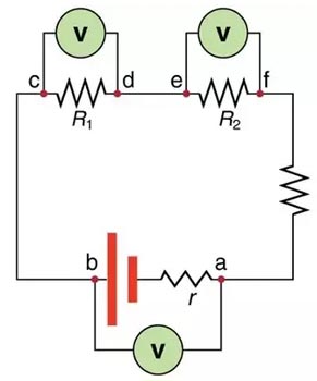
Ques 22. ______ Remain same in all parts of a series circuit
- Current✓
- Resistance
- Voltage
- Power
A series circuit is the simplest type of electrical circuit In a series circuit, there is only one path for current to flow. An electric current is a movement of charges between two points, produced by the applied voltage. As shown in the figure the battery supplies the potential difference that forces free electrons to drift from the negative terminal at A, toward B through the connecting wires and resistances R3, R2, and R1, back to the positive battery terminal at J. At the negative battery terminal, its negative charge repels electrons. Therefore, free electrons in the atoms of the wire at this terminal are repelled from A toward B. Similarly, free electrons at point B can then repel adjacent electrons, producing an electron drift toward C and away from the negative battery terminal. At the same time, the positive charge of the positive battery terminal attracts free electrons, causing electrons to drift toward I and J. As a result, the free electrons inR1 R2, and R3 are forced to drift toward the positive terminal. The positive terminal of the battery attracts electrons just as much as the negative side of the battery repels electrons. Therefore, the motion of free electrons in the circuit starts at the same time and the same speed in all parts of the circuit. The free electrons moving away from one point are continuously replaced by free electrons flowing to an adjacent point in the series circuit. All electrons have the same speed as those leaving the battery. An equal number of electrons move at one time with the same speed. That is why the current is the same in all parts of the series circuit.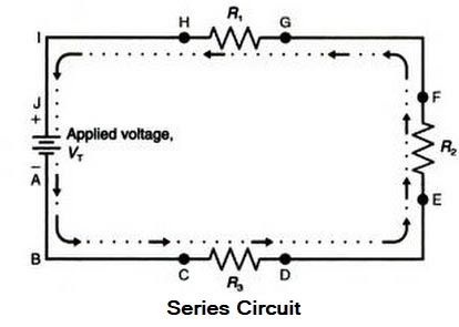
Ques 23. In DC motor, the speed depends upon
- Applied Voltage alone
- Back EMF alone
- Back EMF and flux✓
- Flux Only
The speed of DC motor is directly proportional to the back EMF and inversely proportional to the flux. $N \propto \dfrac{{{E_b}}}{\Phi} = \dfrac{{V – {I_a}{R_a}}}{\Phi}$ Eb depends upon supply voltage and armature voltage drop. In case of motors without any external resistance in the armature circuit, the armature voltage drops are negligible. So, in their case, Eb is mainly dependent upon V and many times when the armature voltage drop is not known, Eb is taken equal to V.
Ques 24. The parallel circuit consists of an inductive branch with R and L as its resistance and inductance, and a capacitance branch with C farad. The impedance offered by the circuit under resonance condition is given by:
- Z = LCR
- Z = R/LC
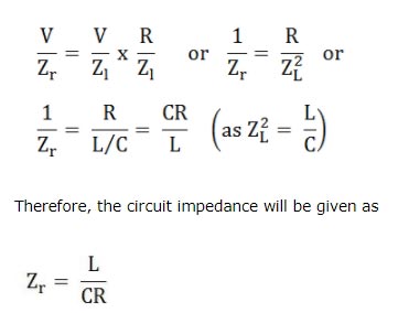
- Z = L/CR✓
- Z = LC/R
A circuit is said to be in resonance when the reactive component or wattless component Isinφ is equal to zero. Consider a parallel circuit consisting of an inductance coil and a capacitor as shown in Fig. Let the current through the inductance L be IL and that through the capacitance C be Ic. if the values of L and C are such that IL = IC then the resultant current I will be equal to IR, i.e. the current flowing through the resistance R. If the circuit consists of only L and C, the currents will be only IL and IC, which oppose each other. Since the induction coil consists of a small but finite resistance R, the current through the inductive circuit will be ${I_R} = \dfrac{V}{Z} = \dfrac{V}{{\sqrt {\left( {{R^2} + {X^2}_L} \right)} }}$ Normally, φ is nearly equal to 90° since the value of R is very small compared to XL. Also, the current through C is IC = V/XC = V/2πfC which leads V by 90°. The above circuit can be said to be in resonance if the resultant circuit current I is in phase with V. Then from the phasor diagram IC = IL sinφ ${I_L} = \dfrac{V}{Z};\sin \Phi = \dfrac{{{X_L}}}{Z};{I_c} = \dfrac{V}{{{X_c}}}$ Putting the value $\begin{array}{l}{I_L} = \dfrac{V}{Z};\sin \Phi = \dfrac{{{X_L}}}{Z};{I_c} = \dfrac{V}{{{X_c}}}\\\\\dfrac{V}{{{X_c}}} = \dfrac{V}{Z} \times \dfrac{{{X_L}}}{Z}\\\\{X_L}{X_c} = {Z^2}\\\\{X_c} = \dfrac{1}{{\omega C}};{X_L} = \omega L\\\\\dfrac{{\omega L}}{{\omega C}} = {Z^2}\\\\Z = \sqrt {\dfrac{L}{C}} \end{array}$ Since the wattless component is zero, therefore, the line current will be line current Ir = IL cosϕ or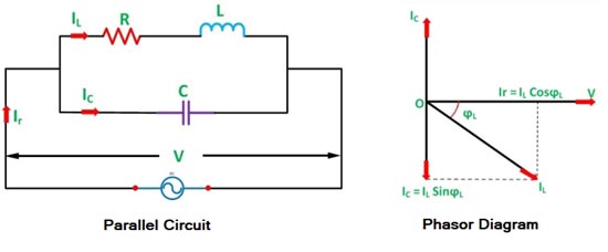
Ques 25. A spherical conductor of radius ‘a’ with charge ‘q’ is placed concentrically inside an uncharged and unearthed spherical conducting shell of inner and outer radii r1 and r2 respectively. Taking potential to be zero at infinity. The potential at any point within the shell (r1 < r < r2) will be?
Ques 26. Convert the Delta network into equivalent star network:
- R1 = 8Ω, R2 = 8Ω, R3 = 8Ω
- R1 = 8Ω, R2 = 16Ω, R3 = 16Ω
- R1 = 8Ω, R2 = 8Ω, R3 = 16Ω
- R1 = 8Ω, R2 = 16Ω, R3 = 8Ω✓
For Resistance P the equation is given as $P = \dfrac{{AB}}{{A + B + C}}$ For resistance Q the equation is $Q = \dfrac{{AC}}{{A + B + C}}$ For resistance R $R = \dfrac{{BC}}{{A + B + C}}$ Hence $P = \dfrac{{20 \times 40}}{{20 + 40 + 40}} = 8\Omega$ $Q = \dfrac{{40 \times 40}}{{20 + 40 + 40}} = 16\Omega$ $R = \dfrac{{20 \times 40}}{{20 + 40 + 40}} = 8\Omega$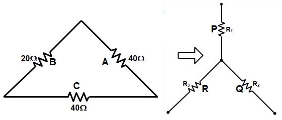
Ques 27. A 2000 / 200V, 20 KVA transformer has 66 turns in the secondary. The number of primary turns are:
- 660✓
- 440
- 770
- 330
A 2000/200 V transformer is one that has normal primary and secondary voltages of 2000 V and 200V respectively. Hence transformer ratio K is given as $\begin{array}{l}K = \dfrac{{{E_2}}}{{{E_1}}} = \dfrac{{{N_2}}}{{{N_1}}}\\\\ = \dfrac{{200}}{{2000}} = \dfrac{{66}}{{{N_1}}}\\\\{N_1} = 660\end{array}$
Ques 28. Induction type energy meter measure energy in______
- Joules
- kW
- kWh✓
- kWs
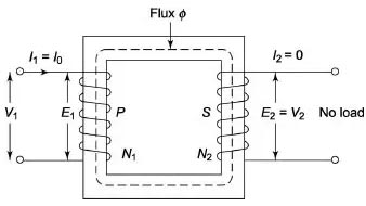
Ques 29. Open circuit test on a transformer gives:
- Total loss
- Insulation resistance
- Core loss✓
- Cu loss
At load, the primary current has two components: Shunt branch current & secondary current when referred to the primary side. At no load, the secondary current becomes zero due to open circuited at secondary. Therefore, only shunt branch component is left which is used to magnetize the transformer coils. The current flowing in coils leads to winding losses. Hence, the current supplied by the source at no load is shunt branch current which is known as No Load Current.
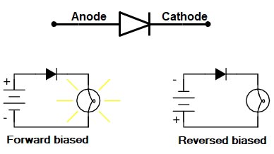
Ques 30. Identify the symbol of isolation transformer among the following
In the isolation transformer, the number of winding in primary and secondary is the same i.e ratio of the winding is in 1:1 In the step-up transformer, the secondary winding is more than the primary In the step-down transformer, the primary winding is more than the secondary winding. Hence option 1 is correct for an Isolation transformer Option B is for step up transformer Option C is for step down transformer Option D is for autotransformer
Ques 31. Compensating winding is used in
- Capacitor Start motor
- Shaded pole Motor
- AC series motor✓
- Capacitor run Motor
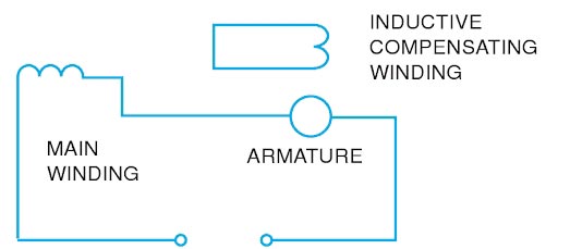
A Universal motor can also refer as the AC series motor which can work on both AC and DC supply. Its construction is very similar to DC series motor. In a normal dc. motor if the direction of both field and armature current is reversed, the direction of torque remains unchanged. So when the normal d.c.series motor is connected to an a.c supply, both field and armature current get reversed and unidirectional torque gets produced in the motor hence motor can work on a.c. supply. But the performance of such motor is not satisfactory due to the following reasons: Now to compensate for increased in the armature reaction, it is necessary to use compensating winding. The flux produced by this winding it opposite to that produced by the armature and effectively neutralizes the armature reaction. If such a compensating winding is connected in series with the armature the motor is said to be ‘conductively compensated‘. For motors to be operated on a.c. and d.c. both, the compensation should be conductive. In the conductively compensated type of motor, an additional compensating winding is placed in slots cut directly into the pole faces. The strength of this field increases with an increase in load current and thus minimizes the distortion of the main field flux by the armature flux called armature reaction,. The compensating winding is connected in series with the series field winding and the armature. Although conductively compensated motors have a high starting torque, the speed regulation is poor. A wide range of speed control is possible with the use of resistor-type starter-controllers. If compensating winding is short-circuited on itself the motor is said to be ‘inductively compensated‘. In this compensating winding acts as a secondary of transformer and armature as its primary. This winding is placed so that it links the cross-magnetizing flux of the armature, which acts as the primary winding of a transformer. Because the magnetomotive force of the secondary is nearly opposite in phase and equal in magnitude to the primary magnetomotive force, the compensating winding flux nearly neutralizes the armature cross flux. This type of motor cannot be used in DC. Because of its dependency on induction, the operating characteristics of an inductively compensated motor art very similar to those of the conductively compensated motor.
Conductive Compensated Winding

Inductive Compensated Winding
Ques 32. Three-point starter can be used for
- Both shunt and compound Motors✓
- Shunt Motor Only
- Series Motor Only
- Compound Motor Only
3 point starters in DC Shunt and Compound machines serve for following purposes.
