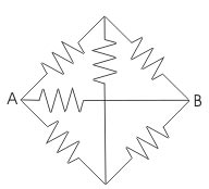
Ques 67. When all the resistance in the given circuit are 1Ω each, the equivalent resistance across point A and B will be?
1 Ω
0.5 Ω✓
3 Ω
2 Ω
All the resistances are the same. Hence it is the condition of a balance wheat stone bridge so no current will flow from 1Ω vertical resistance, so it can be imagined that it is opened. Then the equivalent resistance between A and B is Req = (1+1) || (1+1) || 1 Ω Req = 2 || 2 || 1 Ω Req = 0.5 Ω
Ques 68. When two coils having the coefficient of self-inductance L1 and L2 are coupled through a mutual inductance M. The coefficient of coupling K is given by
K = M/√L1L2✓
K = √L1L2
K = √L1L2/M
None of the above
During Mutual Inductance between two coils, we assume that the flux produced by one coil is entirely linked with the other coil. But practically it is not true, the certain portion of the flux of one coil does not link with the other coil.
The ratio of the portion of the flux of one coil link with the other coil to the entire flux produced by the coil is referred as the coefficient of magnetic coupling.
or
The coupling coefficient K is the degree or fraction of magnetic coupling that occurs between the circuit.
K =M/√L1L2
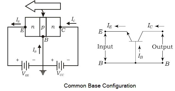
Ques 69. A transistor connected in common base configuration has
High Input resistance and low output resistance
High input resistance and high output resistance
Low Input resistance and high output resistance✓
Low input resistance and low output resistance
In this circuit configuration of a transistor, the base terminal is used as a common terminal between input and output as depicted in Fig. The input signal is applied between the emitter and base terminals. The output will be taken from the collects and base terminals. To explain the operation of NPN and PNP transistors, the common base configuration is used.
Characteristic of common base (CB)
There are two important characteristics of CE
(1) input characteristics.
(2) Output characteristics.
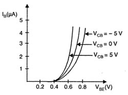
Input Characteristic. It is the curve between base current IB and emitter-base voltage VBE at constant collector-base voltage VCB.
The emitter current IE increases rapidly with a small increase in emitter-baa voltage VEB which means that input resistance is very small.
In fact, the input resistance is the opposition offered to the signal current. As a very small VEB is sufficient to produce a large flow of emitter current, therefore, the input resistance is quite small, of the order of a few ohms.
Output Characteristic. It is the curve between collector current Ic and collector-base voltage VCB at constant emitter current IE. A very large change in collector-base voltage produces only a tiny change in collector current. This means that output resistance is very high.
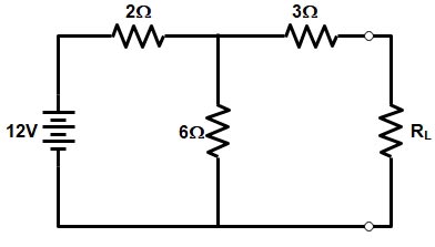
Ques 70. For the given circuit the value of Norton’s equivalent Resistance is:
4.5 Ω✓
5 Ω
6 Ω
10 Ω
Norton equivalent resistance for the given network is
R = (R1 || R2) + R3
R = (2 || 6) + 3 = (2 x 6)(2 + 6) + 3 = 4.5Ω
Ques 71. Method of heating in which the supply circuit is likely to have a leading power factor:
Induction heating
Dielectric heating✓
Resistance heating
Electric arc
Dielectric heating (also called High-frequency capacitive heating) is employed for heating insulators like wood, plastics, ceramics etc.
In dielectric heating, the current is drawn by the capacitor. When an AC supply voltage is applied across the capacitor plates, the current does lead the supply voltage by exactly 90° and there is always an in-phase component of the current. Since the dielectric heating is involved in the capacitor, the power factor will be leading in the case of dielectric heating. The value of the power factor for a particular non-conducting material is constant.
Ques 72. Damping winding in the synchronous Motor
Improve Power factor
Increase Hunting of the motor
Reduces the windage losses
Increase starting torque✓
Damper windings are windings that are wound to the rotor poles of the machine (winding is similar to that of an induction machine) which help in two ways.
We all know that a synchronous machine is not self-starting. Thus providing damper windings help synchronous machines to act as an induction motor ( only at starting). Which helps the machine to self-start.
Ques 73. Bridge suited for measurement of low Q-factor inductance is:
Hay’s bridge
Maxwell’s bridge
Schering bridge
Anderson’s bridge✓
The Q factor of a coil can be measured by measuring accurately the inductance and effective resistance of the coil for a specific signal. The inductance of an inductive coil is generally measured by the usual inductive circuit like Maxwell-Wein Bridge, Hay Bridge, Anderson’s bridge, etc.
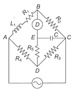
The Anderson’s bridge gives an accurate measurement of the self-inductance of the circuit. The bridge is the advanced form of Maxwell’s inductance capacitance bridge. Anderson bridge is used to measure inductance values over a wide range while only requiring a fixed capacitance of a moderate value. A schematic diagram of the Anderson bridge is shown below. The resistors are chosen such that R1R3 = R2R4. Adjustments of R5 are used to balance the circuit. At balance, the inductance is given by
L=C[R1R3+(R3+R4)R5].
This method is capable of precise measurement of inductance and a wide range of values from a few μH to several Henery.
Ques 74. The rating of the transformer is expressed in:
Copper losses ( I²R) are variable losses that depend on Current passing through transformer windings while Iron Losses Core Losses or Insulation Losses depend on Voltage.
As seen the copper loss of the alternator are dependent upon current and iron loss on voltage. Hence the total loss of the alternator depends on VOLT-AMPERE. These losses are independent of load power factor. That is why the rating of the transformer is in kVA
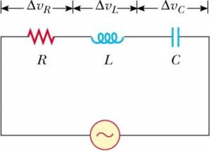
Ques 75. An alternating voltage is given by V = 200 sin314t. It RMS value will be:
110 V
282 .8 V
121. 4 V
141. 4 V✓
The instantaneous value of alternating current is given as