
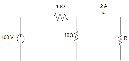
21. Using Norton’s Theorem calculate the equivalent load as shown in the figure
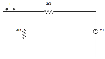
A. 4/3 Ω
B. 4/3 Ω
C. 4 Ω
D. 2 Ω
22. In the following circuit, the value of Norton’s resistance between terminals a and b are ___________
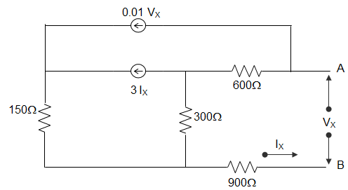
A. RN = 1800 Ω
B. RN = 270 Ω
C. RN = 90 Ω
D. RN = 90 Ω
Answer: D
By writing loop equations for the circuit, we get,
VS = VX, IS = IX
VS = 600(I1 – I2) + 300(I1 – I2) + 900 I1
= (600 + 300 + 900) I1 – 600I2 – 300I3
= 1800I1 – 600I2 – 300I3
I1 = IS, I2 = 0.3 VS
I3 = 3IS + 0.2VS
VS = 1800IS – 600(0.01VS) – 300(3IS + 0.01VS)
= 1800IS – 6VS – 900IS – 3VS
10VS = 900IS
For Voltage, VS = RN IS + VOC
Here VOC = 0
So, Resistance RN = 90Ω.
[/bg_collapse]
23. For the circuit shown in the figure below, the value of Norton’s resistance is _________
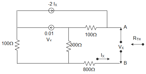
A. 100 Ω
B. 136.4 Ω
C. 200 Ω
D. 272.8 Ω
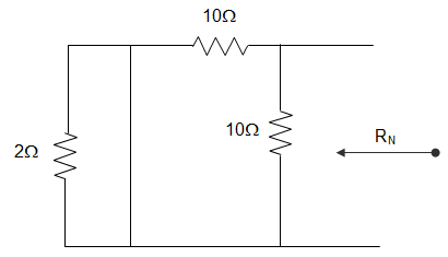
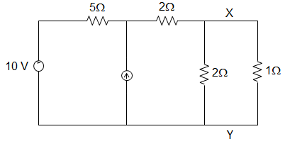
24. For the circuit shown in the figure below, the Norton Resistance looking into X − Y is __________
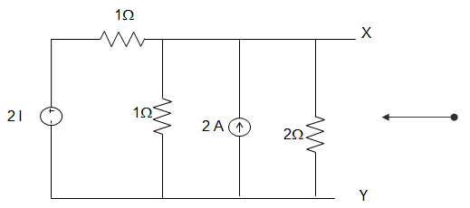
A. 2 Ω
B.2/3 Ω
C. 5/3 Ω
D. 2 Ω
Answer: D
RN = VOC/ISC
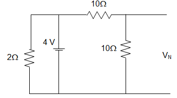
VN = VOC
Applying KCL at node A
\(\frac{2I − V_N}{1} + 2 = I + VN/2
Or, I = VN/1
Putting, 2VN – VN + 2 = VN + VN/2
Or, VN = 4 V.
∴ RN = 4/2 = 2Ω.
[/bg_collapse]
25. In the figure given below, the value of Resistance R by Norton’s Theorem is ___________
A. 40
B. 20
C. 50
D. 80
26. In the figure given below, the Norton Resistance, as seen at the terminals P − Q, is given by __________
A. 5 Ω
B. 7.5 Ω
C. 5 Ω
D. 7.5 Ω
27. The Norton equivalent impedance Z between the nodes P and Q in the following circuit is __________
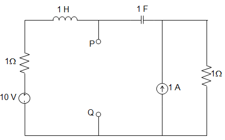
A. 1
B. 1 + s + 1/s
C. 2 + s + 1/s
D. 3 + s + 1/s
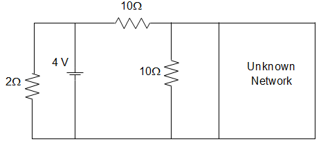
28. In the circuit given below, it is given that VAB = 4 V for RL = 10 kΩ and VAB = 1 V for RL = 2kΩ. The value of Norton resistance for the network N is ________
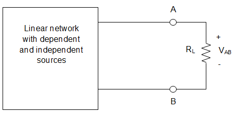
A. 16 kΩ
B. 30 kΩ
C. 3 kΩ
D. 50 kΩ
29. For the circuit given below, Norton’s resistance across the terminals A and B is _________
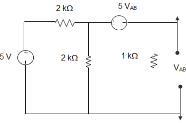
A. 5 Ω
B. 7 kΩ
C. 1.5 kΩ
D. 1.1 kΩ
30. A circuit is given in the figure below. The Norton equivalent as viewed from terminals x and x’s is ___________
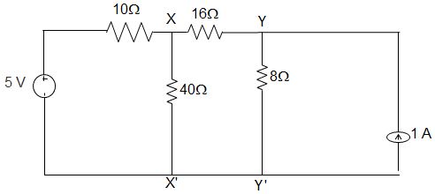
A. 6 Ω and 1.333 A
B. 6 Ω and 0.833 A
C. 32 Ω and 0.156 A
D. 32 Ω and 0.25 A
31. For the circuit given in the figure below, the Norton equivalent as viewed from terminals y and y’ is _________
A. 32 Ω and 0.25 A
B. 32 Ω and 0.125 A
C. 6 Ω and 0.833 A
D. 6 Ω and 1.167 A
We draw the Norton equivalent of the left side of xx’ and source transformed right side of yy’.Norton equivalent as seen from terminal yy’ is
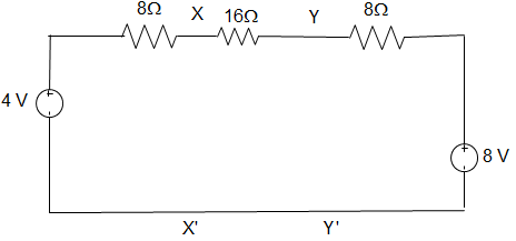
Vxx’ = VN = \(\displaystyle\frac{\frac{4}{8} + \frac{8}{24}}{\frac{1}{8} + \frac{1}{24}}\) = 5V
= (0.167 + 1)/(0.04167 + 0.125) = 7 V
∴ RN = (8 + 16) || 8
= (24×8)/(24 + 8) = 6 Ω
∴IN = VN/RN = 7/6 = 1.167 A.
[/bg_collapse]
32. In the figure given below, the power loss in 1 Ω resistor using Norton’s Theorem is ________
A. 9.76 W
B. 9.26 W
C. 10.76 W
D. 11.70 W
33. The value of RN from the circuit given below is ________
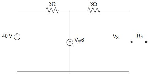
A. 3 Ω
B. 1.2 Ω
C. 5 Ω
D. 12.12 Ω
Answer: D
VX = 3VX/6 + 4
VX = 8 V = VOC
If terminal is short − circuited, VX = 0.
ISC = 4/3 + 3) = 0.66 A
∴ RN = VOC/ISC = 8/0.66 = 12.12 Ω.
[/bg_collapse]
34. By using the Norton equivalent theorem find the current I, as shown in the figure below, is ________
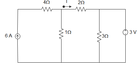
A. 3 A
B. 2 A
C. 1 A
D. 0
35. While computing the Norton equivalent resistance and the Norton equivalent current, which of the following steps are undertaken?
- Both the dependent and independent voltage sources are short-circuited and both the dependent and independent current sources are open-circuited
- Both the dependent and independent voltage sources are open-circuited and both the dependent and independent current sources are short-circuited
- The dependent voltage source is open-circuited keeping the independent voltage source untouched and the dependent current source is short-circuited keeping the independent current source untouched
- The dependent voltage source is short-circuited keeping the independent voltage source untouched and the dependent current source is open-circuited keeping the independent current source untouched