
The peak inverse voltage, in case of a bridge rectifier, for each, the diode is: (where Eo = Peak value of input voltage).
Right Answer is:
Eo
SOLUTION
Peak inverse voltage:- Peak inverse voltage (P.I.V) is the maximum voltage across the diode when it is not conducting. This happens during the negative half of the applied voltage when the diode does not conduct. At this stage, the voltage across the diode is equal to the applied voltage.
Peak Inverse Voltage of the bridge Rectifier:-
Bridge Rectifier:- A bridge circuit acts as a full-wave rectifier without the use of a center-tapped transformer. It consists of four diodes in two pairs D1, D3, and D2, D4, connected to form a bridge as shown in Fig. The A.C supply to be rectified is applied to the diagonally opposite ends of the bridge through a transformer. The load resistance RL is connected between the other Iwo ends of the bridge.
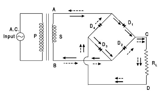
Working:- During the positive half cycle of A.C when the end A of the secondary of the transformer is positive and the end B is negative the diodes D1, D3 is forward biased while the diodes D2, D4 are reverse biased. Therefore, only the diodes D1, D3 conduct and the direction of flow of current are shown by full line arrows. The current flows from A to the first diode D, to C, through the load resistance RL lo D, to the second diode D3, and then to B. thus completing the circuit.
During the negative half-cycle when the end B of the secondary of the transformer is positive and the end A is negative the diodes D2, D4 are forward biased, whereas the diodes D1, D3 are reverse biased. Therefore. only the diodes D2, D4 conduct, and the direction of flow of current is shown by dotted line arrow heads. The current flows from B to the first diode D2 to C through the load resistance RL to D, the second diode D4, and then to A thus completing the circuit. During both the half cycles the current through the load resistance RL, flows in the same direction l.e., C to D. The peak inverse voltage of each diode is equal to the maximum secondary voltage, Eo of the transformer as proved below.
Peak inverse voltage:- If during the half-cycle of a c. input the end A of the secondary of the transformer is positive and end B is negative, diodes D1 and D3 are forward biased, while the diodes D2 and D4 are reverse biased. Since the diodes are considered ideal. the diodes D1 and D3 have negligible forward resistance and can be taken to be simple connecting wires. In such a case the two reverse-biased diodes D2 and D4 and the secondary of the transformer are in parallel. Hence the peak inverse voltage of each diode D2 or D4 is equal to the maximum Eo across the secondary. Similarly, during the next half-cycle, D2 and D4 are forward biased and can be taken to be simple connecting wires. In such a case diodes D1 and D3 and the secondary of the transformer are in parallel. Hence again the peak inverse voltage of D1 or D3. is equal to the maximum voltage Eo.
Hence each diode has only transformer voltage across it on the inverse cycle. In other words, the peak inverse voltage is equal to the peak transformer secondary voltage Em or Eo