Phase Comparator MCQ [Free PDF] – Objective Question Answer for Phase Comparator Quiz

1. Analog phase detector is often referred as

A. Full-wave detector
B. Half wave detector
C. Rectifier wave detector
D. None of the mentioned

Answer: B

An analog phase detector is called a half-wave detector because the phase information for only one-half of the input waveform is detected and averaged.


2. What happens when VCO output is 90o out of phase with respect to the input signal?

A. Perfect lock
B. Attenuation
C. Shift in the phase of comparator
D. Error signal is removed

Answer: A

The error voltage is zero when the phase shift between the two inputs is 90o. So, for the perfect lock, the VCO output should be 90o out of phase with respect to the input signal.


3. Find the error voltage of the phase comparator whose input signal is Vs= Vssin(2πfst) and the output signal Vo= Vosin(2πfot+φ).

A. Ve=[k×(Vs/2)]×[cos(-φ)-cos(2πfot+φ)].
B. Ve=[k×Vs×(Vo/2)]×[cos(-φ)-cos(2πfot+φ)].
C. Ve=[k×Vs×(Vo/2)]×[cos(-φ)+cos(2πfot+φ)].
D. Ve=[k×Vs×Vo]×[cos(-φ)-cos(2πfot+φ)].

Answer: B

A phase comparator is basically a multiplier which multiplies the input signal by the VCO signal.

Thus, the phase comparator output

= Vs×Vo = Vs×Vosin(2πfst)× sin(2πfot+φ)

=k×Vs×Vo ×sin(2πfst)×sin(2πfot+φ)

Where

k – phase comparator gain.

= k×Vs×Vo/2[cos(-φ)-cos(2πfot+φ)]

When at lock, fs =fo

=> Ve = Ve={k×Vs× Vo/2}x[cos(-φ)-cos(2πfot+φ)].


4. How to overcome the problem associated with switch-type phase detective?

A. Increase loop gain depending on the input signal
B. Phase shift is made linear
C. Limit the amplifier of the input signal
D. All of the mentioned

Answer: C

The problems can be eliminated by limiting the amplifier of the input signal that is converting the input to a constant amplified square wave. This can be achieved by using a balanced modulator used as a full-wave switching phase detector.


5. If the average error voltage & the phase shift are given as 6.2v & π/4.Determine the phase angle to voltage transfer coefficient of the full-wave switching phase detector.

A. -0.19
B. -0.09
C. -0.03
D. -0.13

Answer: D

The phase angle to voltage transfer coefficient

=>kφ = (φ-π/2)/ Ve (avg) =[π/4-π/2]/6.2

=[π-2π/4]/6.2 = -(π/4)/6.2 = -π/24.8

=>kφ = -0.13.


6. When does a digital phase detector can be used, where fo->output frequency, fs->input frequency.

A. Both fo & fs signals should be a square wave
B. fo should be square wave & fs can be any non-sinusoidal wave
C. fs should be a square wave & fo can be any non-sinusoidal wave
D. Both fo & fs can be any non-sinusoidal wave

Answer: A

The XOR gate produces high output when only one of the input signals fo or fs is high. So, to detect the high or low values of the waveform, square waves are used.


7. The maximum dc output voltage in the digital phase detector occurs

A. When the phase difference is π/2
B. When the phase difference is π
C. When the phase difference is 3π/4
D. When the phase difference is 2π

Answer: B

The maximum dc output voltage occurs when the phase difference is π because the output of the XOR gate phase detector remains high throughout.


8. Given the DC output voltage versus phase difference φ curve. Find the conversion gain values.
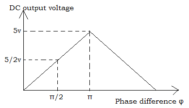
Given the DC output voltage versus phase difference φ curve. Find the conversion gain values.


A. 15.7V/rad
B. 1.26V/rad
C. 1.59V/rad
D. 0.8V/rad

Answer: C

The slope gives the conversion gain. Therefore, conversion gain

=Vcc/φ =5V/π =1.59V/rad.


9. Which among the following has better capture tracking & locking characteristics?

A. XOR phase detector
B. Edge triggered phase detector
C. Analog phase detector
D. All of the mentioned

Answer: B

Edge triggered phase detector has better capture tracking and locking characteristics as the dc output voltage is linear up to 360o compared to other detectors.


10. Which device is used for diagnostic purposes and for recording?

A. Low pass filter
B. Monolithic PLL
C. Voltage Controlled Oscillator
D. None of the mentioned

Answer: C

A Voltage Controlled Oscillator (VCO) is used for converting low-frequency signals such as EEGs, and EKGs into an audio frequency range. These audio signals can be transmitted over two-way radio communication systems for diagnostic purposes or can be recorded on a magnetic tape for further reference.

Scroll to Top