A. (2×Vcc×CT)/i
B. (Vcc CT)/(2×i)
C. (Vcc×CT×i)/2
D. (2×Vcc)/(i×CT)
Answer: B
The time period of VCO is given as
T=2×△t =(2×0.25×Vcc ×CT)/i
=(0.5 V×cc×CT)/i = (Vcc×CT)/(2×i).
12. Determine the value of current flow in VCO, when the NE566 VCO external timing resistor RT =250Ω and the modulating input voltage Vc=3.25V.(Assume Vcc=+5v).
A. 3mA
B. 12mA
C. 7mA
D. 10mA
Answer: C
Current flowing in VCO,
i =(Vcc– Vc)/ RT
= (5V-3.25V)/250
= 1.75/250
=>i =7mA.
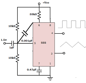
13. From the circuit given, find the value of output frequency?
A. 178.484 Hz
B. 104.84 Hz
C. 145.84 Hz
D. 110.88 Hz
Answer: B
Output frequency,
fo =[2×(Vcc– Vc) ]/(CT×RT×Vcc )
= [2x(8-1.5)]/(0.47µFx33kΩx8v)
=13/0.124
=> fo=104.84 Hz.
14. The output frequency of the VCO can be changed by changing
A. External tuning resistor
B. External tuning capacitor
C. Modulating input voltage
D. All of the mentioned
Answer: D
The output frequency of VCO,
fo = [2×(Vcc– Vc)]/(CT×RT×Vcc).
From the equation, it is clear that the fo is inversely proportional to CT & RT and directly proportional to Vc. Therefore, the output frequency can be changed by changing either voltage control, CT or RT.
15. Calculate the value of the external timing capacitor, if no modulating input signal is applied to VCO. Consider fo=25 kHz and RT=5 kΩ.
A. 6nF
B. 100µF
C. 2nF
D. 10nF
Answer: C
When modulating input signal is not applied to VCO, the output frequency becomes
fo=1/(4×RT×CT)
=> CT =1/(4×RT×fo)
=1/(4×5kΩ×25kHz)
= 2×10-9 =2nF.
16. What is the advantage of using a filter?
A. High noise immunity
B. Reduce the bandwidth of PLL
C. Provides a dynamic range of frequencies
D. None of the mentioned
Answer: A
The charge on the filter capacitor gives a short time memory to the PLL. So, even if the signal becomes less than the noise for a few cycles, the dc voltage on the capacitor continues to shift the frequency of VCO, till it picks up the signal again. This produces high noise immunity.
17. Choose the VCO for attaining a higher output frequency.
A. NE566
B. SE566
C. MC4024
D. All of the mentioned
Answer: C
MC4024 is used for attaining high output frequency because the maximum output frequency of NE566 and SE566 is 500kHz.
18. Voltage to frequency conversion factor for VCO is
A. Kv = △Vc/ △fo
B. Kv = △fo/△Vc
C. Kv = △fo × △Vc
D. Kv = 1/(△fo×△Vc)
Answer: B
The voltage to frequency conversion factor is defined as the change in frequency to the change in modulating input voltage.
=> Kv=△fo/△Vc.
19. Calculate the voltage to frequency conversion factor, where fo=155Hz and Vcc=10V.
A. 130
B. 124
C. 134
D. 116
Answer: B
The voltage to frequency conversion factor,
Kv = △fo/△Vcc=
8×fo/Vcc
= (8×155)/10=124.
20. Find the equation for change in frequency of VCO?
A. △fo = (2×△Vc)/(RT×CT×Vcc)
B. △fo = △Vc/(4×RT×CT×Vcc)
C. △fo = △Vc/(2×RT×CT×Vcc)
D. △fo = (4×△Vc)/(RT×CT×Vcc)