41. To get a maximum output current, IC regulations are provided with
A. Radiation source
B. Heat sink
C. Peak detector
D. None of the mentioned
Answer: B
The load current may vary from 0 to the rated maximum output current. To maintain this condition, the IC regulator is usually provided with a heat sink; otherwise, it may not provide the rated maximum output current.
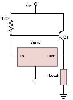
42. For the given circuit, let VEB(ON)=1v, ß= 15 and IO=2mA. Calculate the load current
A. IL = 23.45A
B. IL = 46.32A
C. IL = 56.87A
D. IL = 30.75A
Answer: D
The equation for load current
IL = [(ß+1)IO]-[ß×(VEB(ON)/R1)]
=[(15+1)×2]–[15×(1v/12 Ω)]
=32-1.25 =30.75A.
43. Which type of regulator is considered more efficient?
A. All of the mentioned
B. Special regulator
C. Fixed output regulator
D. Switching regulator
Answer: D
The switching element dissipates negligible power in either on or off state. Therefore, the switching regulator is more efficient than the linear regulators.
44. State the reason for the thermal shutdown of the IC regulator?
A. Spikes in temperature
B. Decrease in temperature
C. Fluctuation in temperature
D. Increase in temperature
Answer: D
The IC regulator has a temperature sensor (built-in) that turns off the IC when it becomes too hot (usually 125oC-150oC. The output current will drop and remains there until the IC has cooled significantly.
45. Find the difference between output current having a load of 100Ω and 120Ω for the 7805 IC regulator. Consider the following specification: Voltage across the load = 5v; Voltage across the internal resistor= 350mv.
A. 8.4mA
B. 7mA
C. 9mA
D. 3.4mA
Answer: A
Given the voltage across the internal resistor to be 350mv, which is less than 0.7v. Hence the transistor in 7805 is off.
When load = 100Ω, IL= IO= Ii= 5v/100 Ω = 50mA
When load=120Ω, IO= 5v/120 Ω = 41.6mA.
So, the difference between the output voltage = 50-41.6mA = 8.4mA.
46. The change in output voltage for the corresponding change in load current in a 7805 IC regulator is defined as
A. All of the mentioned
B. Line regulation
C. Load regulation
D. Input regulation
Answer: C
Load regulation is defined as the change in output voltage for a change in load current and is also expressed in millivolts or as a percentage of output voltage.
47. An IC 7840 regulator has an output current =180mA and an internal resistor =10Ω. Find the collector current in the output using the transistor specification: ß=15 and VEB(ON) =1.5v.
A. 270mA
B. 450mA
C. 100mA
D. 50mA
Answer: B
The collector current from transistor
IC= ßIB
Where
IB= IO-(VEB(ON)/R1)
= 180mA-(1.5v-10Ω) = 0.03A.
Therefore, IC= 15×0.03 = 0.45A = 450mA.
48. How is the average temperature coefficient of output voltage expressed in a fixed voltage regulator?
A. millivolts/oC
B. millivolts
C. None of the mentioned
D. C/ millivolts
Answer: A
The temperature stability or average temperature coefficient of output voltage is the change in the output voltage per unit change in temperature and expressed in millivolts/oC.
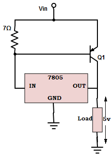
49. In the circuit given below, let VEB(ON)=0.8v and ß=16. Calculate the output current coming from 7805 IC and collector current coming from transistor Q1 for a load of 5Ω.
A. IO =111mA, IC= 808mA
B. IO =111mA, IC= 829mA
C. IO =111mA, IC= 881mA
D. IO =111mA, IC= 889mA
Answer: D
When load = 5Ω, IL= 5v/5Ω =1A.
The voltage across R1 is 7Ω × 1A=7v.
Since IL is more than 100mA, the transistor Q1 turns on and supplies the extra current required.
Therefore
IL =(ß+1)IO-[ß×(VEB(ON)/R1)
IO = [IL/(ß+1)]+ [ß×(VEB(ON)/R1)
= [1/(16+1)]+[16×(0.8/2Ω)] ≅111mA.
=> IC=IL-IO=1A-111mA =889mA.
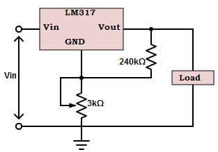
50. Calculate the output voltage for the LM314 regulator. The current IADJ is very small in the order of 100µA. (Assume VREF=1.25v)