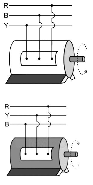
Ques 11. An alternator has a phase sequence of RYB. In case the field current is reversed, the phase sequence will become
RBY
RYB
YRB
YBR
Answer.2. RYB
Explanation:
Reversing an Alternator
The direction of rotation of an alternator is determined by its starting direction, as initiated by induction-motor action.
Thus, to reverse the direction of an alternator, it is necessary to first stop the motor and then reverse the phase sequence of the three-phase connections at the stator like an induction motor.
The direction of rotation of a 3-phase alternator can be changed by altering the phase sequence of the supply. I.e from RBY to RYB. Doing so will change the direction of rotation from clockwise to anticlockwise.
Reversing the current to the field windings will not affect the direction of rotation. If the current in the field winding is reversed the motor will run in the same direction. The field side will only slip through a pole-pitch due to the reversal of the polarities of the field poles.
Ques 12. The gauss-Seidel iterative method can be used for solving a set of
Linear differential equations only
The linear algebraic equation only
Both linear and nonlinear algebraic equations
Both linear and nonlinear differential equations
Answer.2. The linear algebraic equation only
Explanation:
Load flow study determines the operating state of the system for a given loading.
Load flow solves a set of simultaneous non-linear algebraic power equations for the two unknown variables (|V| and ∠δ) at each node in a system.
The output of the load flow analysis is the voltage and phase angle, real and reactive power (both sides in each line), line losses, and slack bus power.
Gauss seidel, Newton Raphson, and the Fast decoupled load flow method are the different load flow methods.
The number of iterations required for convergence of a load flow algorithm increases significantly with the increase of the number of buses with the G-S load flow algorithm.
The fast decoupled load flow method gives an approximate load flow solution because it uses several assumptions. Accuracy depends on the power mismatch vector tolerance.
The fast decoupled load flow method is an extension of the Newton-Raphson method formulated in polar coordinates with certain approximations, which results in a fast algorithm for load flow solution.
The fast decoupled method requires a greater number of iterations than the Newton-Raphson method.
The advantages of the Gauss-Seidel method are:-
A simple algebraic equation is used hence it requires less number arithmetic operations to complete iteration and therefore the time required for each iteration is less
The need for computer memory is less.
This method is most suitable for a small size network.
Ques 13. The pure inductive circuit takes power (reactive) from the AC line when
Both applied voltage and the current rise
Applied voltage decreases but current Increases
Both applied voltage and current decrease
None of these
Answer.2. Applied voltage decreases but current Increases
Explanation:-
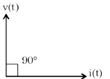
In case of purely inductive circuit, the current in the circuit lags voltage by 90°. Hence calculation of power is positive when multiple of current and voltage is positive.
When the applied voltage decreases toward the zero level, the magnetic field collapses. As the magnetic field collapses, the opposition to current flow decreases.
The decrease in opposition allows current flow to increase.
Current flow is at its maximum or peak value when its opposition is at its minimum value.
The minimum opposition occurs when the applied voltage is also at the minimum value.
Therefore, when the applied voltage is at its minimum, the currentis at its maximum, and when the applied voltage is at its maximum, the current is at its minimum.
In fact, the current reaches its peak value after the voltage has peaked, which in a purely inductive circuit occurs 90° after the voltage peaks.
Therefore, in a purely inductive circuit, the current lags the voltage by 90°. Which is possible when the voltage decreases and the current waveform increases.
Ques 13. A square matrix is called singular if its
Determinant is zero
The determinant is infinity
Rank is unity
None of the above
Answer.1. Determinant is zero
Explanation:
A square matrix that is not invertible is called singular or degenerate.
A square matrix is singular if and only if its determinant is 0.
Singular matrices are rare in the sense that a square matrix randomly selected from a continuous uniform distribution on its entries will almost never be singular.
In linear algebra, an n-by-n square matrix A is called invertible (also nonsingular or nondegenerate) if there exists an n-by-n square matrix B such that AB = BA = In
If we assume that,
A and B are two matrices of the order, n x n satisfying the following condition:
AB = I = BA
Where I denote the identity matrix whose order is n.
Then, matrix B is called the inverse of matrix A.
Therefore, A is known as a non-singular matrix.
Ques 14. In load flow analysis, the load connected to a bus is represented as
Constant impedance connected to the bus
Voltage and frequency-dependent source at the bus
Constant real and reactive drawn from the bus
Constant current is drawn from the bus
Answer.3. Constant real and reactive drawn from the bus
Explanation:
Power-flow or load-flow studies are important for planning the future expansion of power systems as well as in determining the best operation of existing systems. Load flow studies determine if system voltages remain within specified limits under normal or emergency operating conditions and whether equipment such as transformers and conductors are overloaded. A load flow study is the steady-state analysis of the power system network.
Bus types
Depending, upon which two variables you specify, the buses (nodes) can be categorized into three categories:
Slack bus (swing or reference bus)
PQ bus (also called as load bus)
PV bus (generator bus)
PQ bus
Normally in a power system, the real and reactive power quantities are specified and so the load connected at the bus in load flow analysis is represented as constant real and reactive power drawn from the bus. PQ buses are also called load buses and may contain generators with specified real and reactive power outputs.
Slack bus
There is only one slack bus in the system under consideration. The slack bus always has a generator attached to it, with no exception. Normally this generator is the biggest in the system. Its two main tasks are to:
Serve as the reference for voltage angle
Balance generation, load, and losses, because the power losses are not known until the end of load flow calculation. The slack bus needs to supply losses.
PV bus
The PV buses can have voltage control capabilities and use a tap-adjustable transformer and/or VAR compensator instead of a generator. PV buses are also called voltage-controlled buses.
To solve non-linear algebraic equations it is important to have fast, efficient, and accurate numerical algorithms.
The output of the load flow analysis is the voltage and phase angle, real and reactive power (both sides in each line), line losses, and slack bus power.
Constant parameters of different buses in load flow studies:
Bus Name
Specified or constant values
Unknown values
Load bus
Real and reactive power
Voltage and load angle
Generator bus
Real power and voltage
Reactive power and load angle
Slack bus
Voltage, load angle is equal to 00
Real and reactive power
Voltage-controlled bus
Real power and voltage
Reactive power, load angle is equal to 00
Ques 15. If transformer frequency is changed from 50 Hz to 60 Hz the ratio of eddy current loss 50 Hz to 60 Hz, at constant voltage will be
1
2
5/6
25/36
Answer.4. 25/36
Explanation:
Eddy current loss in the transformer is given by:
Pe = Ke Bm2. t2. f2. V Watts
Where;
K – coefficient of eddy current. Its value depends upon the nature of magnetic material
Bm – Maximum value of flux density in Wb/m2
t – Thickness of lamination in meters
f – Frequency of reversal of the magnetic field in Hz
Ques16. When a d.c source is switched in purely inductive, the current response is
Increase exponentially and reach a constant value
Exponentially decaying curve
A straight line passing through the origin
A straight line offset from the origin
Answer.3. A straight line passing through the origin
Explanation:
Energy is stored in the electromagnetic field of an inductor when it is connected to a dc voltage source. The buildup of current through the inductor occurs in a predictable manner, which is dependent on the time constant of the circuit.
Switching of DC is an example of step excitation
The current through the inductor is given by:
$V = L\frac{{di}}{{dt}}$
$\frac{V}{L} = \frac{{di}}{{dt}}$
Since V is step excitation, V/L is also step excitation
$\frac{{di}}{{dt}} = step\;response$
Integrating the above expression
$i = ramp\;response$
Hence current through the inductor is a straight line passing through the origin.
Ques 17. A 3-phase, 3-line, 100 Km long transmission line is loaded at 110 kV. If the loss per phase is 5 MW and the load is 150 MVA, the resistance of the line is.
8.06 ohms per phase
0.806 ohms per phase
0.0806 ohms per phase
80.6 ohms per phase
Answer.1. 8.06 ohms per phase
Explanation:
3 phase power loss can be calculated as
PL = 3 Vp Ip cosϕ
PL = √3 VL IL cosϕ
Where,
Vp = Phase voltage
Ip = Phase current
VL = Line voltage
IL = Line current
Power loss per phase-
PL = I2 x R
Calculation:
All the calculations are done in per phase only-
Now load current (I) can be calculated as
I = (150 x 106)/(√ 3(110 x 103)) per phase
I = (15 / 11√ 3) x 103
Now, using power loss Formula-
PL = I2 x R
5 x 106 = (225/121× 3) x106 x R
So, R = 8.06 ohm/phase
Ques 18. At a particular unbalanced node, the real powers specified are
Leaving the node 20 MW, 25 MW
Entering the node 60 MW, 30 MW
Then the balanced power will be
30 MW leaving the node
45 MW leaving the node
45 MW entering the node
22.5 MW entering and 22.5 MW leaving the node
Answer.3. 45 MW entering the node
Explanation:
According to Kirchhoff’s current law (KCL) at any node (junction) in an electrical circuit, the sum of currents flowing into that node is equal to the sum of currents flowing out of that node.
Sum of power entering the node 60 + 30 =90 MW
Sum of power leaving the node 20 + 25 = 45
To make the power flow balanced sum of power entering the node must be equal to the sum of power leaving the node. Hence the sum of power entering the node must be equal to 45 MW.
Ques 19. Series capacitive compensation on EHV transmission lines is used to
Reduce the line loading
Improve the stability of the system
Reduce the voltage profile
Improve the protection of the line
Answer.2. Improve the stability of the system
Explanation:
The change in the electrical characteristics of a transmission line in order to increase its power transmission capability is known as line compensation.
Reactive compensation is used to improve the performance of the transmission line. Generally, there are two types of compensation:
Shunt
Series
Series Compensation: In this type of compensation, the capacitor bank is connected in series with the transmission line. As a result, the net reactance of the line is reduced. The series capacitive compensation decrease the overall effective series transmission impedance from the sending end to the receiving end. Hence it increases the power system stability. It also reduces the net reactive voltage drop of the line. Thus, the performance of the line is improved. The power transfer capability of a transmission line can be written as
$P = \frac{{{V_S}.{V_R}.\sin \delta }}{{{X_L}}}$
Where
VS= Sending end voltage
VR = Receiving end voltage
δ = Angle between two voltage vectors
XL = Line reactance
Advantages of series compensation
A series compensated a capacitor is an effective tool for line reactance compensation. The equivalent line reactance in this case will be XL − XC. 50% compensation is generally used.
Increase in transmission capacity.
More power can be transferred from one end to another by double circuit (parallel) lines. But, instead, a series-compensated line is cheaper as one can transmit more power through a single line.
Better voltage regulation and improved voltage profile are possible at the load end as a series capacitor can supply reactive power during heavy load periods.
The stability limit is improved.
Series capacitors are inherently self-regulating and a control system is not required.
For the same performance, series capacitors are often less costly than SVCs and losses are very low.
For voltage stability, series capacitors lower the critical or collapse voltage.
Series capacitors possess the adequate time-overload capability.
Series capacitors and switched series capacitors can be used to control the loading of parallel lines to minimize active and reactive losses.
Disadvantages of series compensation:
Series capacitors are line connected and compensation is removed for outages and capacitors in parallel lines may be overloaded.
During heavy loading, the voltage on one side of the series capacitor may be out of range.
Shunt reactors may be needed for light load compensation.
Subsynchronous resonance may call for expensive countermeasures.
Shunt Compensation: In this type of compensation, either shunt inductors or shunt capacitors are used. They are connected between each line and neutral to reduce the effect of shunt susceptance of the line.
Shunt inductors are also known as shunt reactors. It absorbs the reactive power from the lines and controls the voltage of the line when the line is at no load or is lightly loaded. They are connected at both the ends of transmission lines.
With the help of shunt capacitor banks, reactive power is injected into the line to maintain the voltage within the limits at heavy loads. The shunt capacitors are connected near the load terminals.
Ques 20. The transmission line feeding power on either side of the main transmission line is called as
Primary distribution
Primary transmission
Secondary distribution
Secondary transmission
Answer.4.Secondary transmission
Explanation:
The transmission line feeding power on either side of the main transmission line is called secondary transmission.
Detailed explanation
At the generating station, electrical power is generated with the help of three-phase alternators running in parallel. In the scheme shown, the voltage level is 11 kV but the voltage level may be 6.6 kV, 22 kV, or 33 kV depending upon the capacity of the generating station. After the generating station, actual transmission and distribution start.
Primary transmission: It is basically with the help of overhead transmission lines. For the economic aspects, the voltage level is increased to 132 kV, 220 kV or more, with the help of a step-up transformer. Hence this transmission is also called high voltage transmission. The primary transmission uses 3 phase 3 wire system.
Secondary transmission:
The transmission line feeding power on either side of the main transmission line is called secondary transmission.
The primary transmission line continues via transmission towers till the receiving stations.
At the receiving stations, the voltage level is reduced to 22 kV or 33 kV using the step-down transformer.
There can be more than one receiving station.
Then at the reduced voltage level of 22 kV or 33 kV, the power is then transmitted to various substations using an overhead 3 phase 3 wire system.
This is the secondary transmission.
The conductors used for the secondary transmission are called feeders.